Power Module Package Structure

A power module and packaging structure technology, applied in the directions of support structure installation, closed chassis, circuit devices, etc., can solve the problem of reducing the cross-over area of ​​the current loop without ink, etc., to reduce the cross-over area, reduce the current density, The effect of reducing loop inductance

Active Publication Date: 2020-02-07
DELTA ELECTRONICS INC
View PDF5 Cites 0 Cited by
  • Summary
  • Abstract
  • Description
  • Claims
  • Application Information

AI Technical Summary

Problems solved by technology

Depend on Figure 2A , 2B It can be seen that the structure of the power module 100B is mainly improved for these terminals (31B, 32B, 33B), but there is no ink on the reduction of the crossover area of ​​the current loop of the power module 100B.

Method used


Image

  • Power Module Package Structure
  • Power Module Package Structure
  • Power Module Package Structure

Examples


Embodiment Construction

[0097] Below in conjunction with accompanying drawing, structural principle and working principle of the present invention are specifically described:

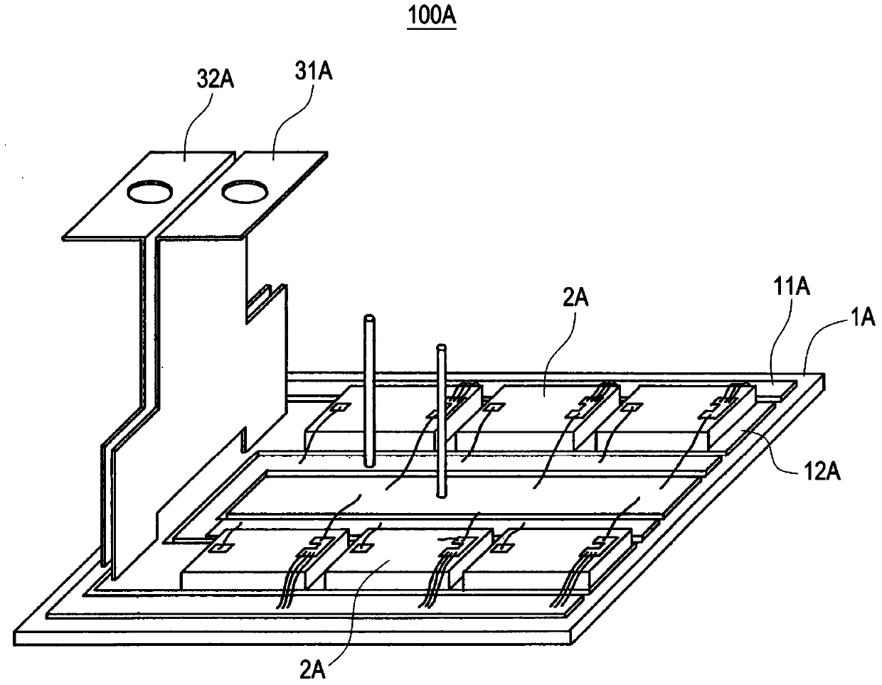
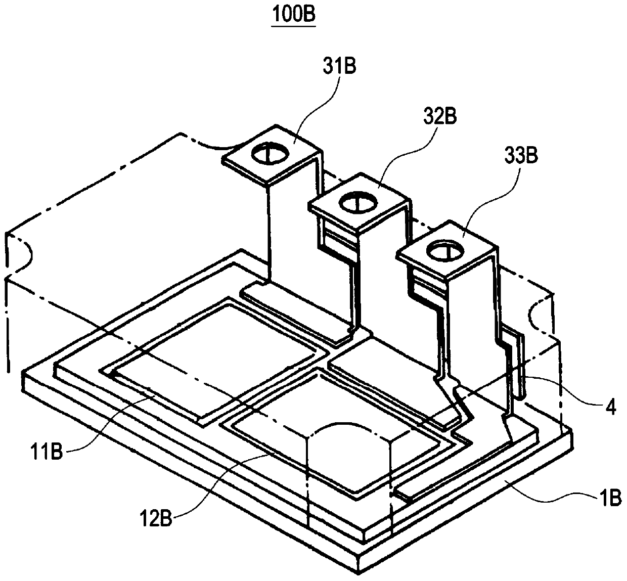
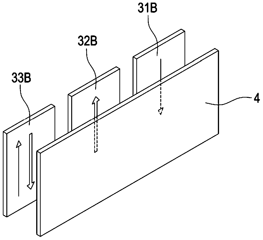
[0098] see image 3 It is a three-dimensional exploded view of the packaging structure of the power module of the present invention. The power module 100 includes: a substrate 1 , and the substrate 1 at least includes a first conductive region 11 , a second conductive region 12 and a third conductive region 13 . And there is a first connection region 14 between the first conductive region 12 and the second conductive region 13 , and the first connection region 14 is electrically connected to the first conductive region 11 through the substrate 1 . There is a second connection region 15 between the second conduction region 12 and the third conduction region 13 , and the second connection region 15 is electrically connected to the second conduction region 12 through the substrate 1 . The first conductive region 11, the second ...


PUM


Abstract

A power module packaging structure, the power module includes: a substrate with a first conductive region, a second conductive region, a third conductive region, a first fixed connection region and a second fixed connection region, the first conductive region, the first conductive region The two conductive regions and the third conductive region are electrically connected to the first terminal, the second terminal and the third terminal, and the first switch group and the second switch group are electrically connected by the first fixed connection region and the second fixed connection region , so as to achieve mutual parallel arrangement between each other. The first terminal is a current input terminal, the second terminal is a relay terminal, and the third terminal is a current output terminal. When the current flows from the current input terminal to the relay terminal, or from the relay terminal to the current output terminal, the current takes a straight line path to reduce the crossover area of ​​the power module current loop and reduce the loop leakage inductance.

Description

technical field [0001] The invention relates to a package structure of a power module, in particular to a package structure of a power module with low loop leakage inductance. Background technique [0002] In today's industrial automation or electric vehicle field, the demand for inverters with high withstand voltage and high load is increasing day by day, so the design of the power module also faces many challenges, one of which is the terminal connecting the power module with the external circuit. The shape and arrangement of the terminals will affect the leakage inductance of the power module. If the design is not proper, the leakage inductance will be too high, and the product with low withstand voltage will be easily damaged. In addition, terminals are usually soldered to the substrate by solder. Due to the difference in thermal expansion coefficient between the terminal and the substrate, the solder at the joint between the terminal and the substrate is prone to cracks...

Claims


Application Information

Patent Timeline
Patent Type & Authority Patents(China)
IPC IPC(8): H01L23/538H01L23/31
CPCH01L2224/0603H01L2224/48227H01L2224/49111H01L2224/49113H01L23/053H05K1/0263H05K2201/10272H05K1/0268H01L25/072H01L25/115H05K5/0247H05K7/1401H05K5/0069H05K5/0013
Inventor 纪伟豪廖学国
Owner DELTA ELECTRONICS INC
Why Eureka
Try Eureka