Lighting source and lighting apparatus

a technology of light source and light source, which is applied in the direction of electric lighting source, electroluminescent light source, and semiconductor lamp usage, etc., can solve the problems of inability to switch between only the emission colors without changing brightness and power consumption, and achieve the effect of simplifying the optical mechanism for adjusting the light distribution properties

Active Publication Date: 2015-03-19
PANASONIC INTELLECTUAL PROPERTY MANAGEMENT CO LTD
View PDF1 Cites 75 Cited by
  • Summary
  • Abstract
  • Description
  • Claims
  • Application Information

AI Technical Summary

Benefits of technology

[0021]According to a lighting source and a lighting apparatus of an embodiment of the present invention, since, among light-emitting units each having a different emission color, a light-emitting unit having a greater number of light-emitting elements connected in series has a greater total forward voltage, a first switch element switches between current paths of the light-emitting units, and a constant power output circuit

Problems solved by technology

The LED module disclosed in PTL 1, however, has a configuration for changing the emission color of the LED module 900 according to

Method used


Image

  • Lighting source and lighting apparatus
  • Lighting source and lighting apparatus
  • Lighting source and lighting apparatus

Examples


embodiment 1

[0043]First, a straight tube LED lamp 1 according to Embodiment 1 of the present invention is described. It is to be noted that the straight tube LED lamp 1 according to this embodiment substitutes for a conventional straight tube fluorescent lamp.

[Entire Configuration of Lamp]

[0044]First, a configuration of the straight tube LED lamp 1 according to this embodiment of the present invention is described with reference to FIG. 1 and FIG. 2.

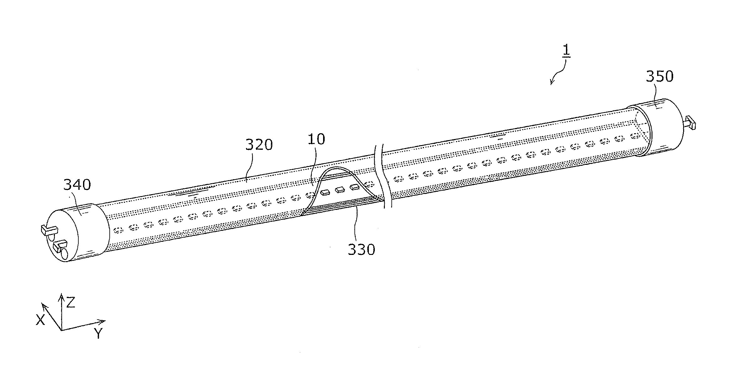
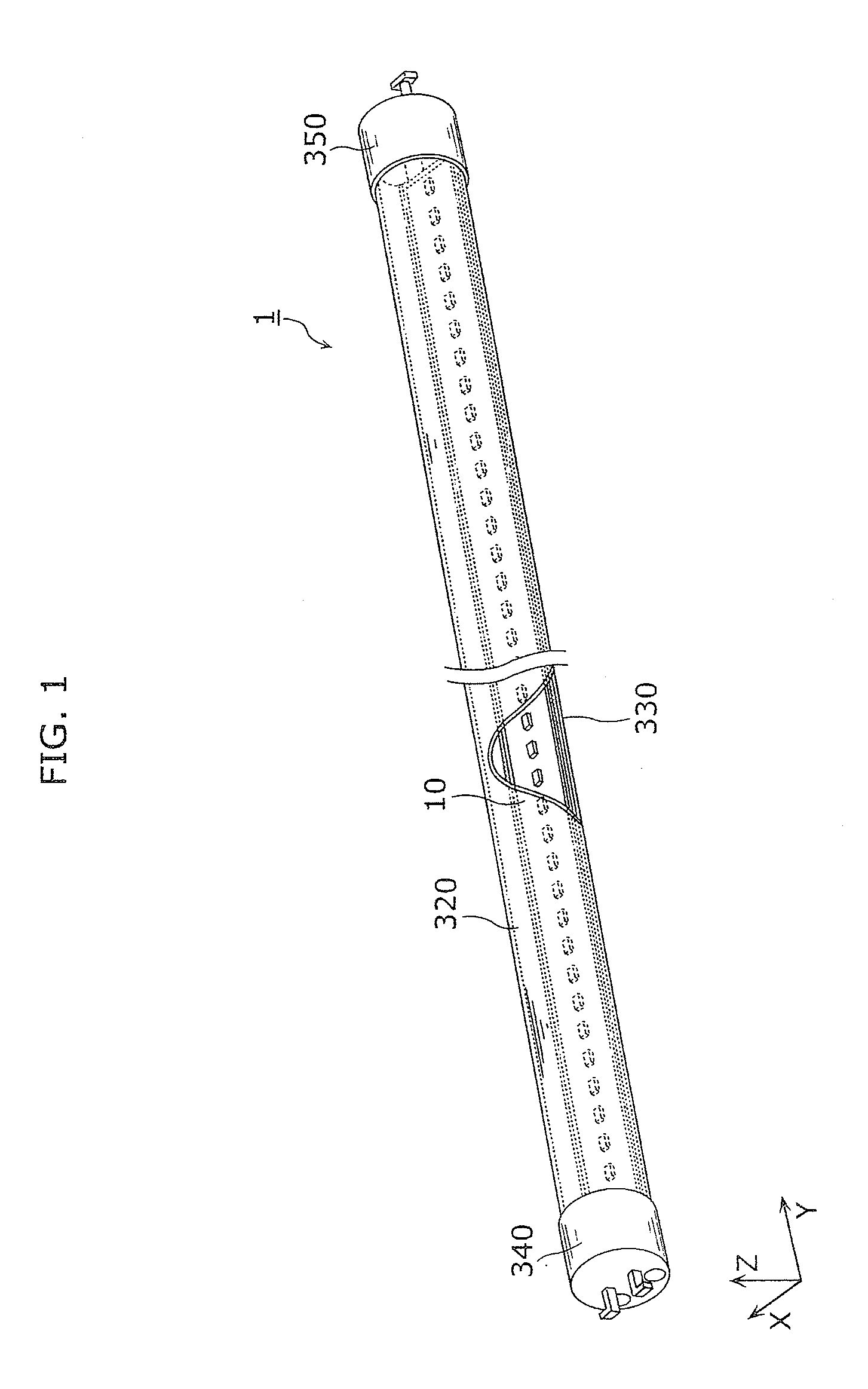
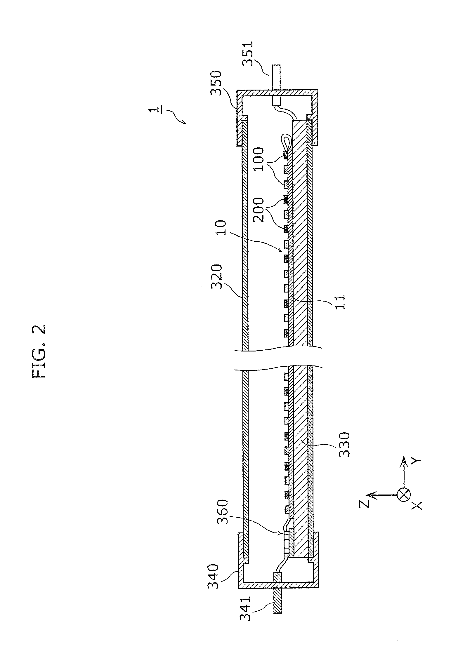
[0045]FIG. 1 is a general perspective view of a straight tube LED lamp according to this embodiment. FIG. 2 is a cross-sectional view in a tube axis direction of the straight tube LED lamp according to this embodiment. As shown in FIG. 1, the straight tube LED lamp 1 is a lighting source including: an LED module 10; an elongated case 320 that houses the LED module 10; a base platform 330; a feeding base (feeding-side base) 340 provided to one of end portions in a longitudinal direction (tube axis direction) of the case 320; a non-feeding base 350 pr...

embodiment 2

[0119]The following describes a lighting apparatus 2 according to Embodiment 2 of the present invention with reference to FIG. 9.

[0120]FIG. 9 is a general perspective view of a lighting apparatus according to Embodiment 2. As shown in the figure, the lighting apparatus 2 according to this embodiment is a base light and includes straight tube LED lamps 1 and a lighting appliance 400.

[0121]Each of the straight tube LED lamps 1 is the straight tube LED lamp 1 according to Embodiment 1, and is used as a lighting source of the lighting apparatus 2. It is to be noted that two straight tube LED lamps 1 are used in this embodiment.

[0122]The lighting appliance 400 includes: pairs of sockets 410 electrically connected to and holding the straight tube LED lamps 1; and an appliance body 420 to which the sockets 410 are attached. The appliance body 420 can be formed by press working an aluminum steel sheet, for instance. Moreover, the inner surface of the appliance body 420 is a reflective surfa...


PUM


Abstract

A straight tube LED lamp according to one aspect of the present invention includes: a first LED array including first LED elements connected in series; a second LED array that includes second LED elements connected in series, and emits light having a different emission color from an emission color of the first LED array; a FET switch provided in a path through which current flows to the second LED array; and a constant power output circuit that outputs power without changing a total value of the power, wherein the number of the first LED elements connected in series is greater than the number of the second LED elements connected in series, a total forward voltage of the first LED array is greater than a total forward voltage of the second LED array, and the first LED elements are in alignment with the second LED elements.

Description

CROSS REFERENCE TO RELATED APPLICATION[0001]This application claims the benefit of priority of Japanese Patent Application Number 2013-190978, filed Sep. 13, 2013, the entire content of which is hereby incorporated by reference.TECHNICAL FIELD[0002]The disclosure relates to a lighting source including light-emitting elements such as light-emitting diodes (LEDs), and to a lighting apparatus including the lighting source.BACKGROUND ART[0003]In recent years, a lighting apparatus using a light-emitting module including semiconductor light-emitting elements such as LEDs has gained in popularity as a substitute for an incandescent light bulb. In general, a change in level of current flowing through an LED chip does not change the emission color of the LED chip. This is because the emission color of the LED chip depends on the bandgap of a semiconductor material included in the LED chip, but does not depend on the current level.[0004]In view of the above, Patent Literature (PTL) 1 (Japanes...

Claims


Application Information

Patent Timeline
IPC IPC(8): H05B33/08H05B44/00
CPCH05B33/0857H05B33/0815H05B45/40H05B45/20Y02B20/30H05B45/3578H05B45/3725
Inventor TAKAHASHI, AKIRATAKEDA, KAZUHIRO
Owner PANASONIC INTELLECTUAL PROPERTY MANAGEMENT CO LTD
Why Eureka
Try Eureka