Lighting source and lighting apparatus

a technology of light source and light source, which is applied in the direction of electric lighting source, electroluminescent light source, and semiconductor lamp usage, etc., can solve the problems of inability to switch between only the emission colors without changing brightness and power consumption, and achieve the effect of easy light distribution adjustment and simplified optical mechanism

Inactive Publication Date: 2015-03-19
PANASONIC INTELLECTUAL PROPERTY MANAGEMENT CO LTD
View PDF4 Cites 16 Cited by
  • Summary
  • Abstract
  • Description
  • Claims
  • Application Information

AI Technical Summary

Benefits of technology

[0021]According to a lighting source and a lighting apparatus of an embodiment of the present invention, since, among light-emitting units each having a different emission color, a light-emitting unit having a greater number of light-emitting elements connected in series has a greater total forward voltage, a first switch element switches between current paths of the light-emitting units, and a constant power output circuit supplies constant power to the light-emitting units, it is possible to switch between emission colors without changing brightness and power consumption. Moreover, since, among two light-emitting units, a first light-emitting unit having a greater number of light-emitting elements connected in series is annularly provided in an outer circumference region on a board, light distribution adjustment is made readily, and an optical mechanism can be simplified.

Problems solved by technology

The LED module disclosed in PTL 1, however, has a configuration for changing the emission color of the LED module 900 according to light adjustment, and is incapable of switching between only the emission colors without changing brightness and power consumption.

Method used


Image

  • Lighting source and lighting apparatus
  • Lighting source and lighting apparatus
  • Lighting source and lighting apparatus

Examples


embodiment 1

Configuration of Lighting Apparatus

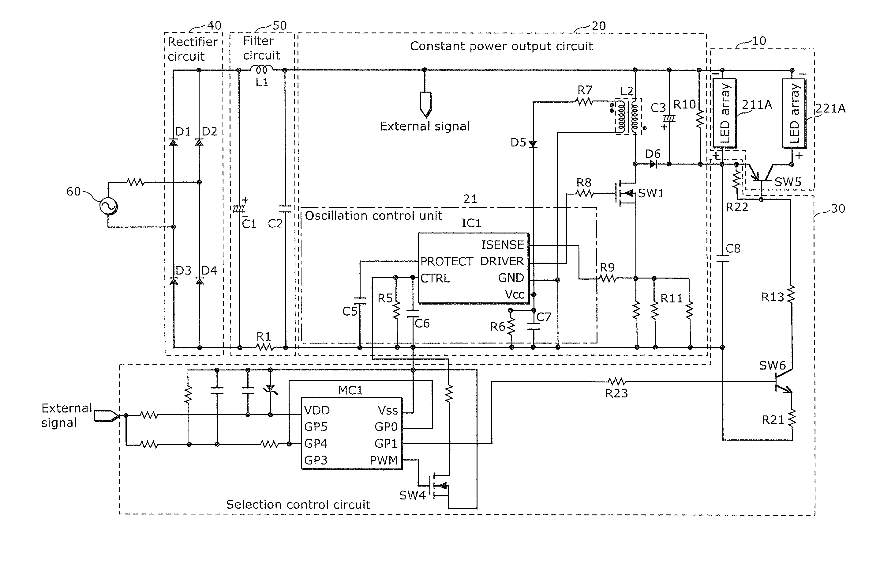
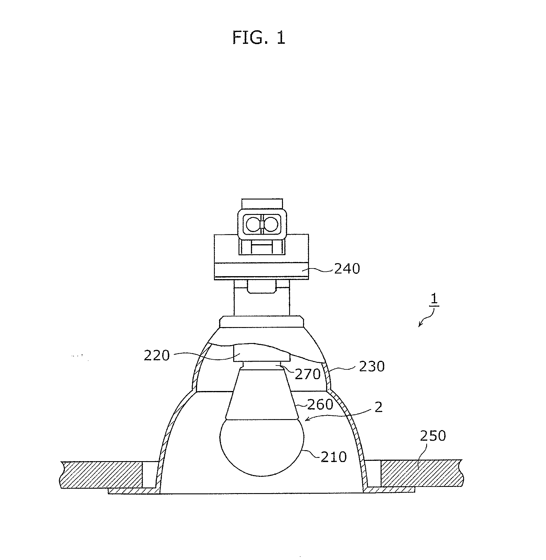
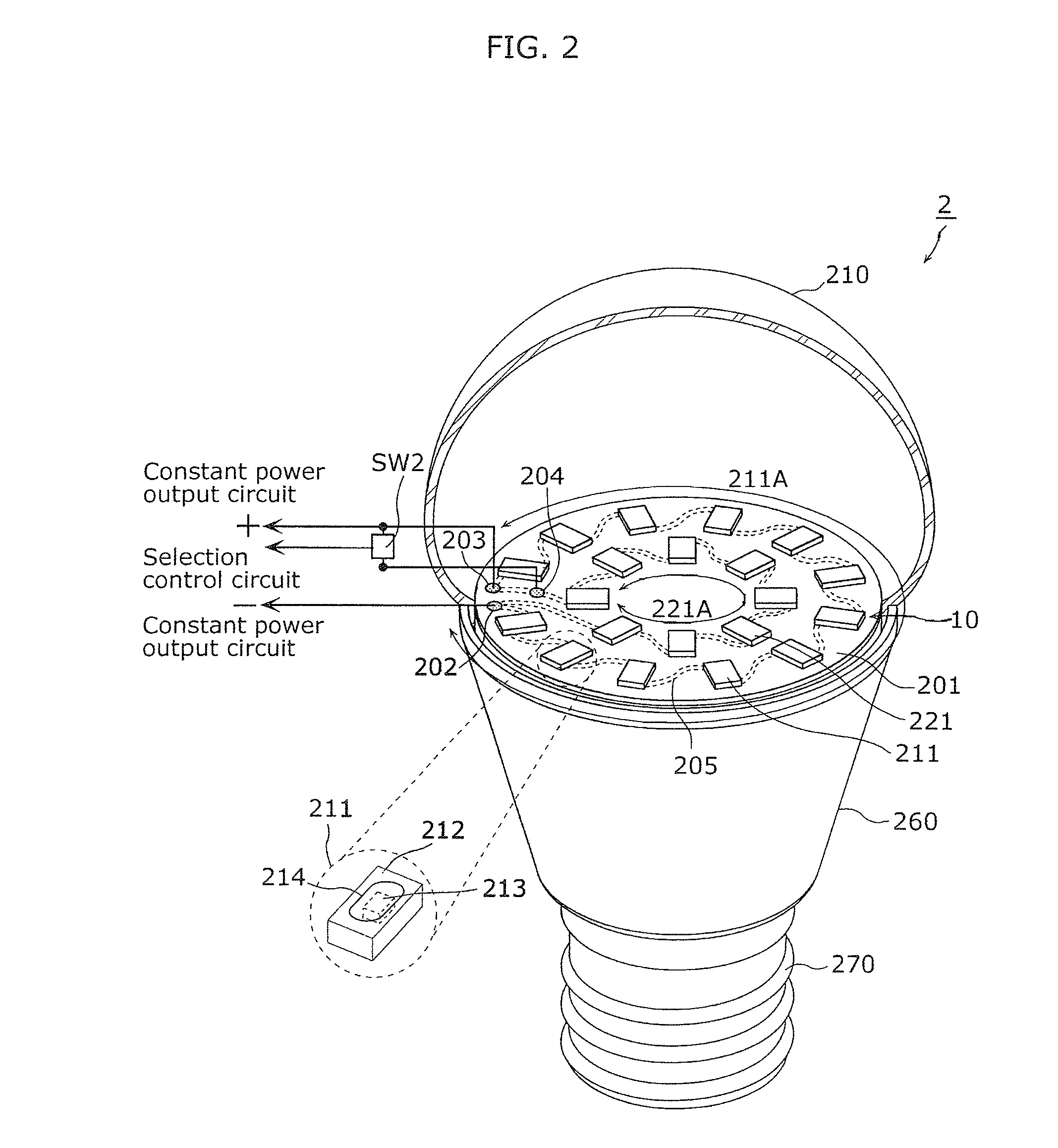
[0043]FIG. 1 is a cross-sectional view of a lighting apparatus including an LED lamp according to Embodiment 1. As shown in FIG. 1, an LED lamp 2 is attached to a lighting apparatus 1. The LED lamp 2 is a lighting source that includes a globe 210, an outer case 260, and a base 270, and houses an LED module 10 (not shown in FIG. 1). Furthermore, a selection control circuit that switches between switch elements according to an external signal, and a constant power output circuit (not shown in FIG. 1) that supplies constant power to the LED module 10, are provided inside the outer case 260 and the base 270. With this configuration, the constant power is supplied to an LED array selected according to the external signal, and the LED lamp 2 emits light having the emission color of the selected LED array.

[0044]The lighting apparatus 1 includes: the LED lamp 2, a socket 220 which is electrically connected to the LED lamp 2 and which holds the LED lamp 2; ...

embodiment 2

[0113]Hereinafter, an LED lamp according to Embodiment 2 is described with reference to the drawings. It is to be noted that the description of the same configuration as the LED lamp 2 according to Embodiment 1 is omitted, and different configurations from the LED lamp 2 are mainly described below.

[Configuration of LED Module]

[0114]FIG. 8 is an exemplary layout view of components in the LED module according to Embodiment 2. An LED module 11 according to this embodiment is attached to the LED lamp 2 shown in FIG. 1.

[0115]The LED module 11 is a light-emitting module including: LED elements 311; LED elements 321 having a different emission color from an emission color of the LED elements 311; the FET switch SW2 provided in a second current path through which current flows to the LED elements 321.

[0116]The LED elements 311 are annularly arranged in an outer circumferential region on a mounting board 301, and are connected in series to each other. Moreover, the LED elements 311 are also ...

embodiment 3

[0123]Hereinafter, an LED lamp according to Embodiment 3 is described with reference to the drawings. It is to be noted that the description of the same configuration as the LED lamp 2 according to Embodiment 1 is omitted, and different configurations from the LED lamp 2 are mainly described below.

[Configuration of LED Module]

[0124]FIG. 9 is an exemplary layout view of components in an LED module according to Embodiment 3. An LED module 12 according to this embodiment is attached to the LED lamp 2 shown in FIG. 1. Alternatively, the LED module 12 according to this embodiment is attached as a light-emitting module of a straight tube LED lamp.

[0125]The LED module 12 is a light-emitting module including: LED elements 411; LED elements 421 having a different emission color from an emission color of the LED elements 411; the FET switch SW2 provided in a second current path through which current flows to the LED elements 421.

[0126]The LED elements 411 are arranged in an outer circumferent...


PUM


Abstract

An LED lamp according to one aspect of the present invention includes: a first LED array that is annularly arranged on a mounting board and includes first LED elements connected in series; a second LED array that is arranged within an inner circumference of the first LED array on the mounting board, includes second LED elements connected in series, and emits light having an emission color different from an emission color of the first LED array; a FET switch arranged in series on a path through which current flows to the second LED array; and a constant power output circuit, wherein the number of the first LED elements is greater than the number of the second LED elements, and a total forward voltage of the first LED array is greater than a total forward voltage of the second LED array.

Description

CROSS REFERENCE TO RELATED APPLICATION[0001]This application claims the benefit of priority of Japanese Patent Application Number 2013-190990, filed Sep. 13, 2013, the entire content of which is hereby incorporated by reference.TECHNICAL FIELD[0002]The disclosure relates to a lighting source including light-emitting elements such as light-emitting diodes (LEDs), and to a lighting apparatus including the lighting source.BACKGROUND ART[0003]In recent years, a lighting apparatus using a light-emitting module including semiconductor light-emitting elements such as LEDs has gained in popularity as a substitute for an incandescent light bulb. In general, a change in level of current flowing through an LED chip does not change the emission color of the LED chip. This is because the emission color of the LED chip depends on the bandgap of a semiconductor material included in the LED chip, but does not depend on the current level.[0004]In view of the above, Patent Literature (PTL) 1 (Japanes...

Claims


Application Information

Patent Timeline
Patent Type & Authority Applications(United States)
IPC IPC(8): H05B33/08H05B44/00
CPCH05B33/0857H05B33/0815H05B45/40H05B45/20Y02B20/30H05B45/3725
Inventor TAKAHASHI, AKIRATAKEDA, KAZUHIRO
Owner PANASONIC INTELLECTUAL PROPERTY MANAGEMENT CO LTD
Why Eureka
Try Eureka