Lighting source and lighting apparatus

a technology applied in the field of light source and lighting apparatus, can solve the problems of inability to switch between light-emitting characteristics such as emission colors without changing brightness and power consumption, and achieve the effect of reducing the number of circuit components, and reducing brightness and power consumption

Inactive Publication Date: 2016-06-28
PANASONIC INTELLECTUAL PROPERTY MANAGEMENT CO LTD
View PDF8 Cites 3 Cited by
  • Summary
  • Abstract
  • Description
  • Claims
  • Application Information

AI Technical Summary

Benefits of technology

[0009]The present invention has been conceived in view of the above problem, and an object of the present invention is to provide a lighting source and a lighting apparatus that are capable of minimizing the number of circuit components for switching between the light-emitting characteristics, and switching between the light-emitting characteristics without changing the brightness and the power consumption.
[0020]Since a lighting source and a lighting apparatus according to an embodiment of the present invention each include LED arrays each having a different total forward voltage, and a constant power output circuit, and minimize the number of circuit components for switching between driving of the LED arrays, the lighting source and the lighting apparatus are capable of reducing the number of the circuit components and switching between light-emitting characteristics without changing brightness and power consumption.

Problems solved by technology

The LED module disclosed in PTL 1, however, has a configuration for changing the emission color of the LED module 900 according to light adjustment, and is incapable of switching between light-emitting characteristics such as emission colors without changing brightness and power consumption.

Method used


Image

  • Lighting source and lighting apparatus
  • Lighting source and lighting apparatus
  • Lighting source and lighting apparatus

Examples


embodiment 1

[0042][Configuration of Lighting Apparatus]

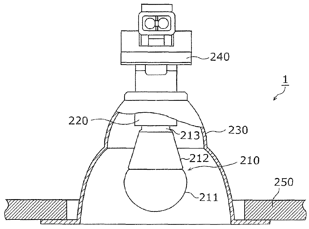
[0043]FIG. 1A is a cross-sectional view of a lighting apparatus including an LED lamp according to Embodiment 1. As shown in FIG. 1A, an LED lamp 210 is attached to a lighting apparatus 1. The LED lamp 210 is a lighting source that includes a globe 211, an outer case 212, and a base 213, and houses an LED module 10 (not shown in FIG. 1A). Furthermore, a selection control circuit that switches between switch elements according to an external signal, and a constant power output circuit (not shown in FIG. 1A) that supplies constant power to the LED module 10, are provided inside the outer case 212 and the base 213. With this configuration, the constant power is supplied to an LED array selected according to the external signal, and the LED lamp 210 emits light having the emission color of the selected LED array.

[0044]The lighting apparatus 1 includes: the LED lamp 210, a socket 220 which is electrically connected to the LED lamp 210 and which ...

embodiment 2

[0104]Hereinafter, an LED lamp according to Embodiment 2 is described with reference to the drawings. It is to be noted that the description of the same configuration as the LED lamp 210 according to Embodiment 1 is omitted, and different configurations from the LED lamp 210 are mainly described below.

[0105][Configuration of LED Lamp]

[0106]This embodiment describes a lighting source capable of switching between light distribution properties with the same power consumption by causing the FET switch SW2 to switch between current paths of current flowing through two LED arrays.

[0107]FIG. 6 is a perspective view of an LED lamp according to Embodiment 2. An LED lamp 360 is attached to the lighting apparatus 1 shown in FIG. 1A. The LED lamp 360 includes a globe 361, an outer case 362, and a base 363, and houses an LED module 300. Furthermore, the selection control circuit 30 that switches between switch elements according to an external signal, and the constant power output circuit 20 (no...


PUM


Abstract

An LED lamp according to one aspect of the present invention including: a first LED array including first LED elements connected in series; a second LED array that includes second LED elements connected in series and emits light having an emission color different from an emission color of the first LED array; a FET switch that is provided between the two LED arrays and switches between a first current path to the first LED array and a second current path to the second LED array; a constant power output circuit that outputs the same power value to a current path through which current flows before the switching and a current path through which current flows after the switching, wherein a total forward voltage of the first LED array is different from a total forward voltage of the second LED array.

Description

CROSS REFERENCE TO RELATED APPLICATION[0001]This application claims the benefit of priority of Japanese Patent Application Number 2013-191004, filed Sep. 13, 2013, the entire content of which is hereby incorporated by reference.TECHNICAL FIELD[0002]The disclosure relates to a lighting source including light-emitting elements such as light-emitting diodes (LEDs), and to a lighting apparatus including the lighting source.BACKGROUND ART[0003]In recent years, a lighting apparatus using a light-emitting module including semiconductor light-emitting elements such as LEDs has gained in popularity as a substitute for an incandescent light bulb. In general, a change in level of current flowing through an LED chip does not change the emission color of the LED chip. This is because the emission color of the LED chip depends on the bandgap of a semiconductor material included in the LED chip, but does not depend on the current level.[0004]In view of the above, Patent Literature (PTL) 1 (Japanes...

Claims


Application Information

Patent Timeline
Patent Type & Authority Patents(United States)
IPC IPC(8): H05B37/02H05B33/08H05B44/00
CPCH05B33/0815H05B33/086H05B33/0857H05B45/20H05B45/3725
Inventor TAKAHASHI, AKIRATAKEDA, KAZUHIRO
Owner PANASONIC INTELLECTUAL PROPERTY MANAGEMENT CO LTD
Why Eureka
Try Eureka