Beamforming Microphone Array with Support for Interior Design Elements

a technology of microphone array and interior design, which is applied in the direction of mouthpiece/microphone attachment, loudspeaker, instruments, etc., can solve the problems of inability to meet video or teleconference conference rooms, the installation cost of the array involves an additional cost of a ceiling-mount or wall-mount system for the array

Active Publication Date: 2015-03-19
CLEARONCE COMM INC
View PDF8 Cites 58 Cited by
  • Summary
  • Abstract
  • Description
  • Claims
  • Application Information

AI Technical Summary

Problems solved by technology

However, it is not practical for a video or teleconference conference room since the color scheme, size, and geometric shape of the array might not blend well with the décor of the conference room.
Also, the cost of installation of the array involves an additional cost of a ceiling-mount or a wall-mount system for the array.

Method used


Image

  • Beamforming Microphone Array with Support for Interior Design Elements
  • Beamforming Microphone Array with Support for Interior Design Elements
  • Beamforming Microphone Array with Support for Interior Design Elements

Examples


Embodiment Construction

[0032]This disclosure describes a Beamforming Microphone Array with Support for Interior Design Elements. This disclosure describes numerous specific details in order to provide a thorough understanding of the present invention. One having ordinary skill in the art will appreciate that one may practice the present invention without these specific details. Additionally, this disclosure does not describe some well-known items in detail in order not to obscure the present invention.

Non-Limiting Definitions

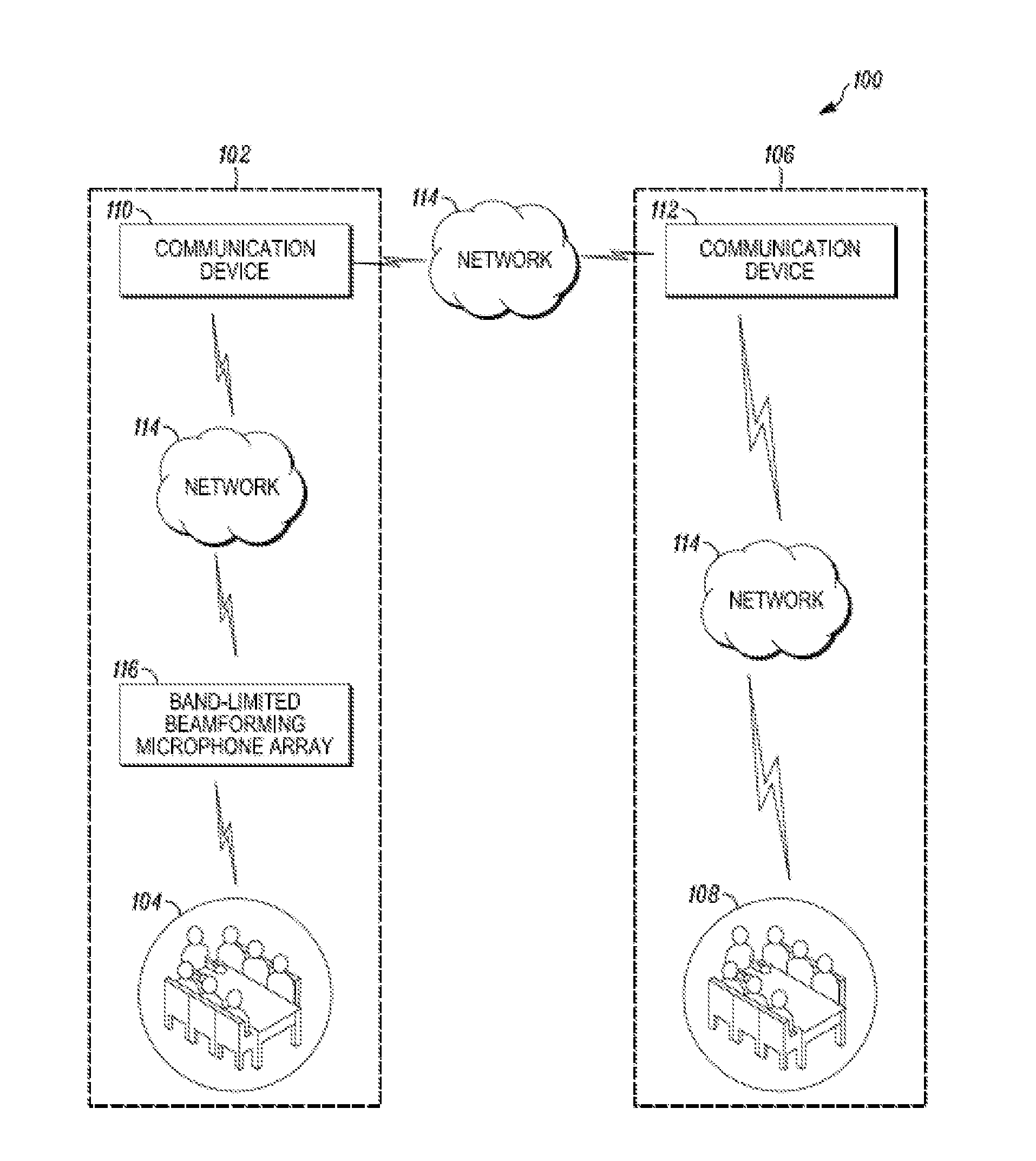
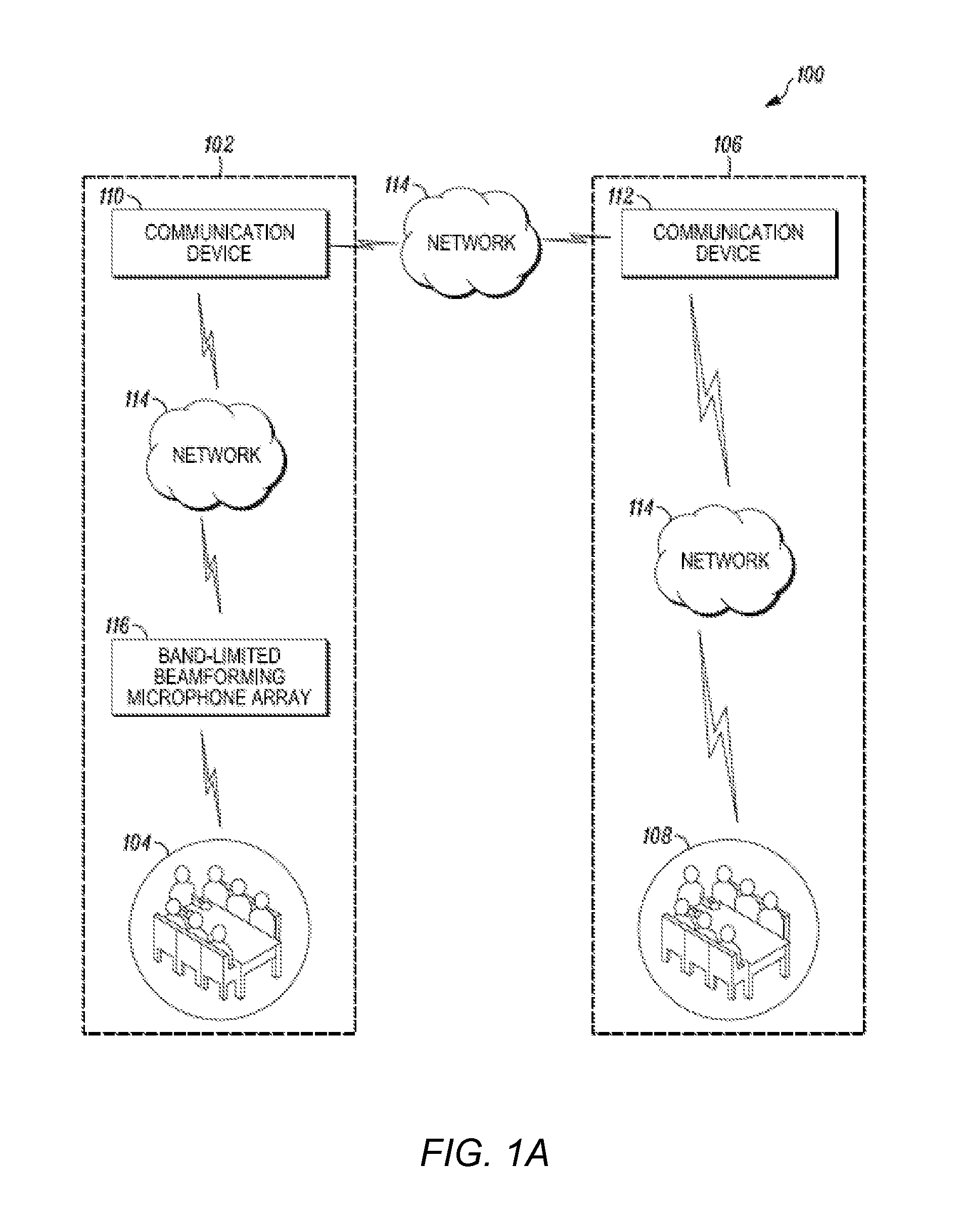
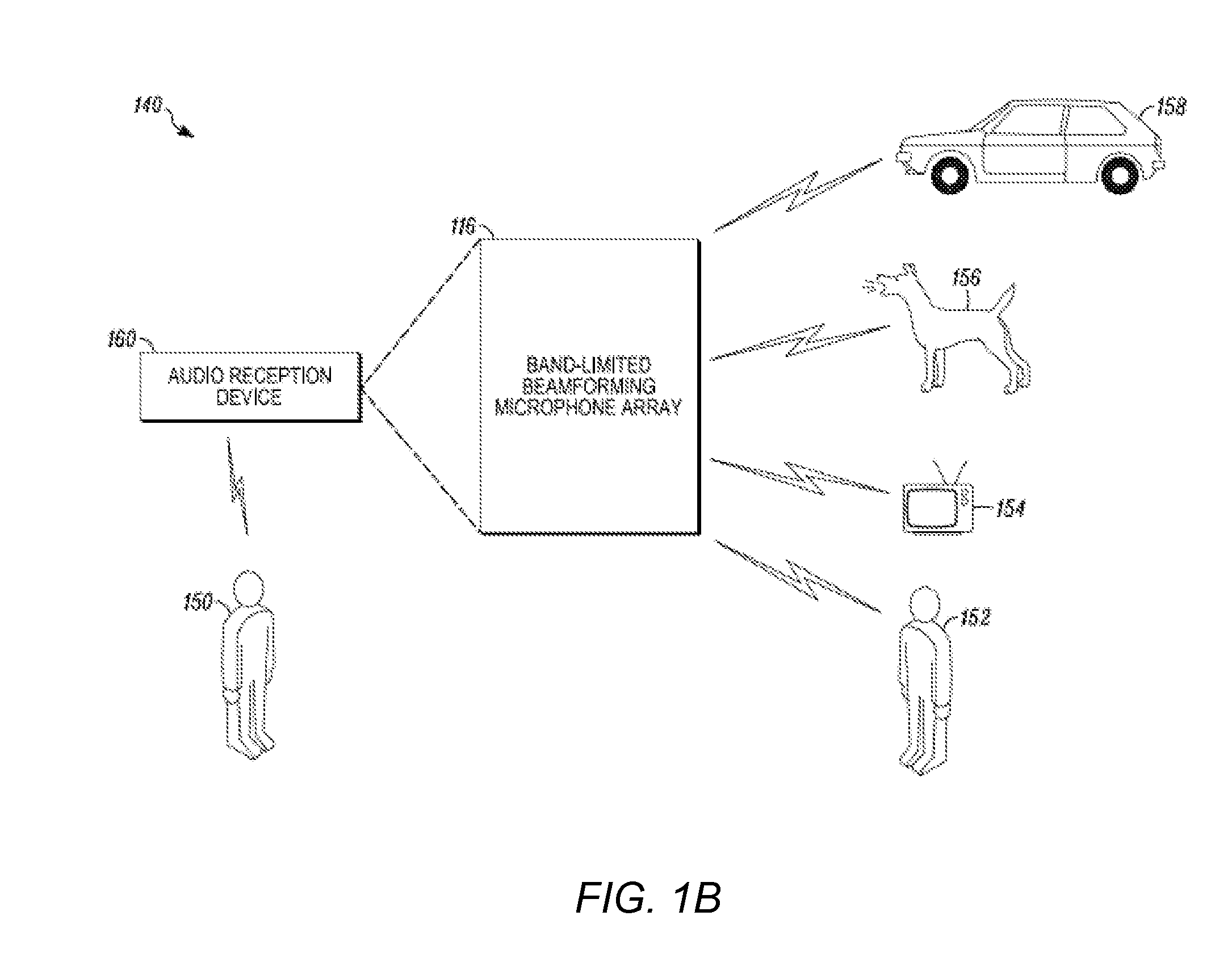
[0033]In various embodiments of the present disclosure, definitions of one or more terms that will be used in the document are provided below. A “beamforming microphone” is used in the present disclosure in the context of its broadest definition. The beamforming microphone may refer to a microphone configured to resolve audio input signals over a narrow frequency range received from a particular direction.

[0034]A “non-beamforming microphone” is used in the present disclosure in the co...


PUM


Abstract

Embodiments of the present disclosure include an apparatus (210, 230, 240, 250) configured to perform beamforming on multiple audio input signals. The apparatus (210, 230, 240, 250) includes one or more illumination devices (222, 232, 242, 252) and a beamforming microphone system (116) integrated with the one or more illumination devices. The beamforming microphone system (116) includes a first plurality of microphones (302, 502) configured to resolve first audio input signals within a first frequency range. The beamforming microphone system (116) also includes at least one microphone (504) configured to resolve second audio input signals within a second frequency range. A lowest frequency in the first frequency range is greater than a lowest frequency in the second frequency range.

Description

CROSS REFERENCE TO RELATED APPLICATIONS[0001]This application claims priority and the benefits of the earlier filed Provisional U.S. 61 / 771,751, filed 1 Mar. 2013, which is incorporated by reference for all purposes into this specification.[0002]This application claims priority and the benefits of the earlier filed Provisional U.S. 61 / 828,524, filed 29 May 2013, which is incorporated by reference for all purposes into this specification.[0003]Additionally, this application is a continuation of U.S. application Ser. No. 14 / 191,511, filed 27 Feb. 2014, which is incorporated by reference for all purposes into this specification.[0004]Additionally, this application is a continuation of U.S. application Ser. No. 14 / 276,438, filed 13 May 2014, which is incorporated by reference for all purposes into this specification.TECHNICAL FIELD[0005]This disclosure relates to beamforming microphone arrays. More specifically, this disclosure invention relates to beamforming microphone array systems w...

Claims


Application Information

Patent Timeline
Patent Type & Authority Applications(United States)
IPC IPC(8): H04R3/00H04R17/02
CPCH04R17/02H04R3/005H04R2430/23H04R2201/021H04R1/406H04R1/08G10L21/0232G10L2021/02082H04R29/005H04R3/04H04R1/2876H04R31/006H04R2420/07H04R2430/21
Inventor GRAHAM, DEREKLAMBERT, DAVID K.BRAITHWAITE, MICHAEL
Owner CLEARONCE COMM INC
Why Eureka
Try Eureka