AI technical title is built by PatSnap AI team. It summarizes the technical point description of the patent document.
a technology of implanted and anchors, which is applied in the field of valve repair, can solve the problems of reducing cardiac output, reducing total stroke volume, and ultimate weakening of the left ventricl
Active Publication Date: 2015-03-19
VALTECH CARDIO LTD
View PDF4 Cites 121 Cited by
Summary
Abstract
Description
Claims
Application Information
AI Technical Summary
This helps you quickly interpret patents by identifying the three key elements:
Problems solved by technology
Method used
Benefits of technology
Benefits of technology
[0102]In some embodiments of the present invention, a delivery system is provided for positioning and anchoring of the annuloplasty structures described herein to the annulus of the patient. The delivery system comprises an advancement catheter housing (a) the annuloplasty structure in a distal portion thereof, and (b) a steerable catheter disposed proximally with respect to the annuloplasty structure. A plurality of guide members are reversibly coupled to the annuloplasty structure and to the steerable catheter. These guide members facilitate steering of the steerable catheter toward specific locations along the annuloplasty structure. Typically, by pulling on the proximal end of a given guide member, the distal end of the catheter is steered toward a given location of annuloplasty structure.
[0392]In an embodiment, the distance between the proximal rotational subunits restricts the proximal rotational subunits from being corkscrewed around the bar and into the annulus of the patient.
Problems solved by technology
Mitral regurgitation of blood from the left ventricle into the left atrium results in increased total stroke volume and decreased cardiac output, and ultimate weakening of the left ventricle secondary to a volume overload and a pressure overload of the left atrium.
Method used
Image
Click on the blue label to locate the original text in one second.
Reading with bidirectional positioning of images and text.
Examples
Embodiment Construction
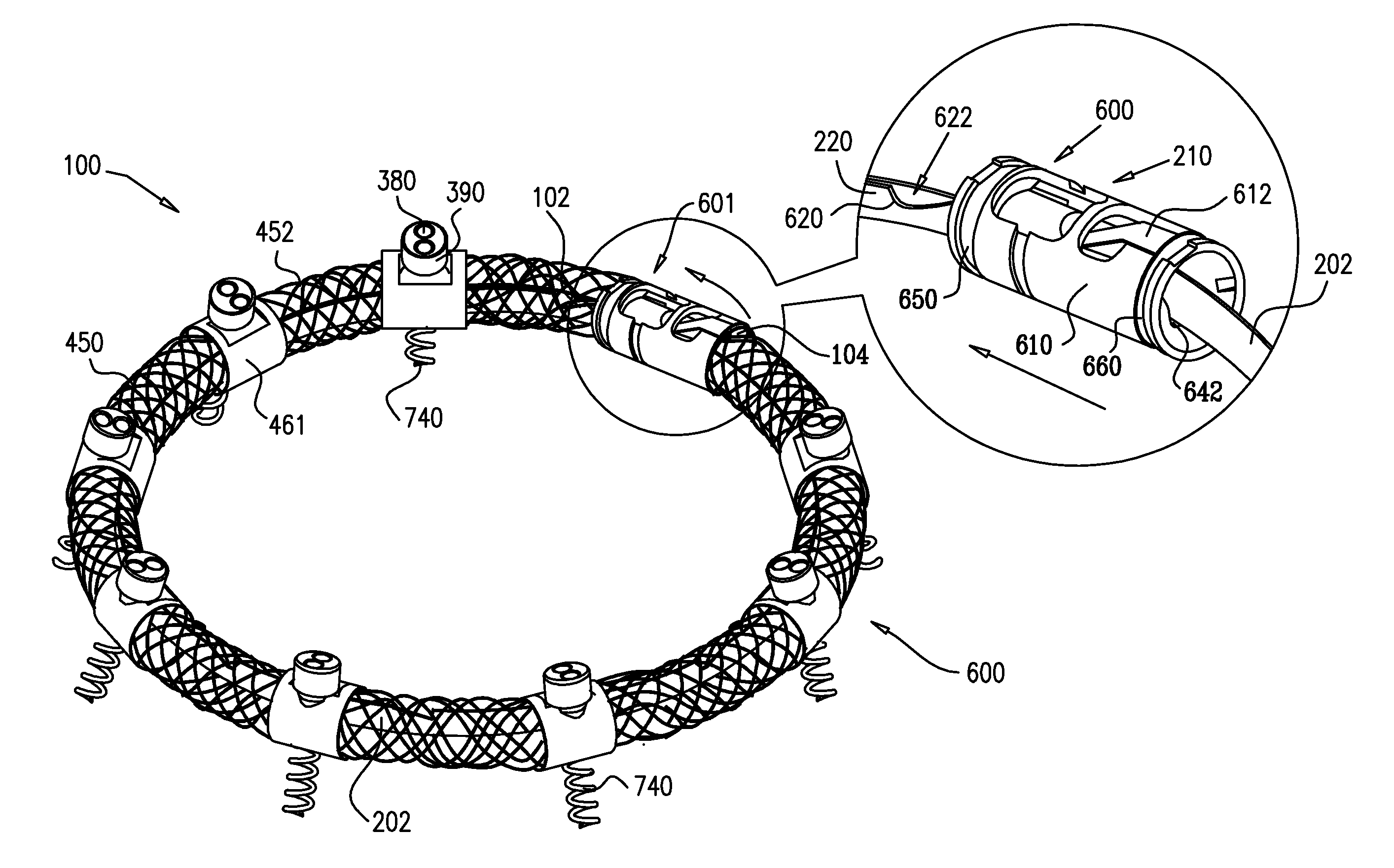
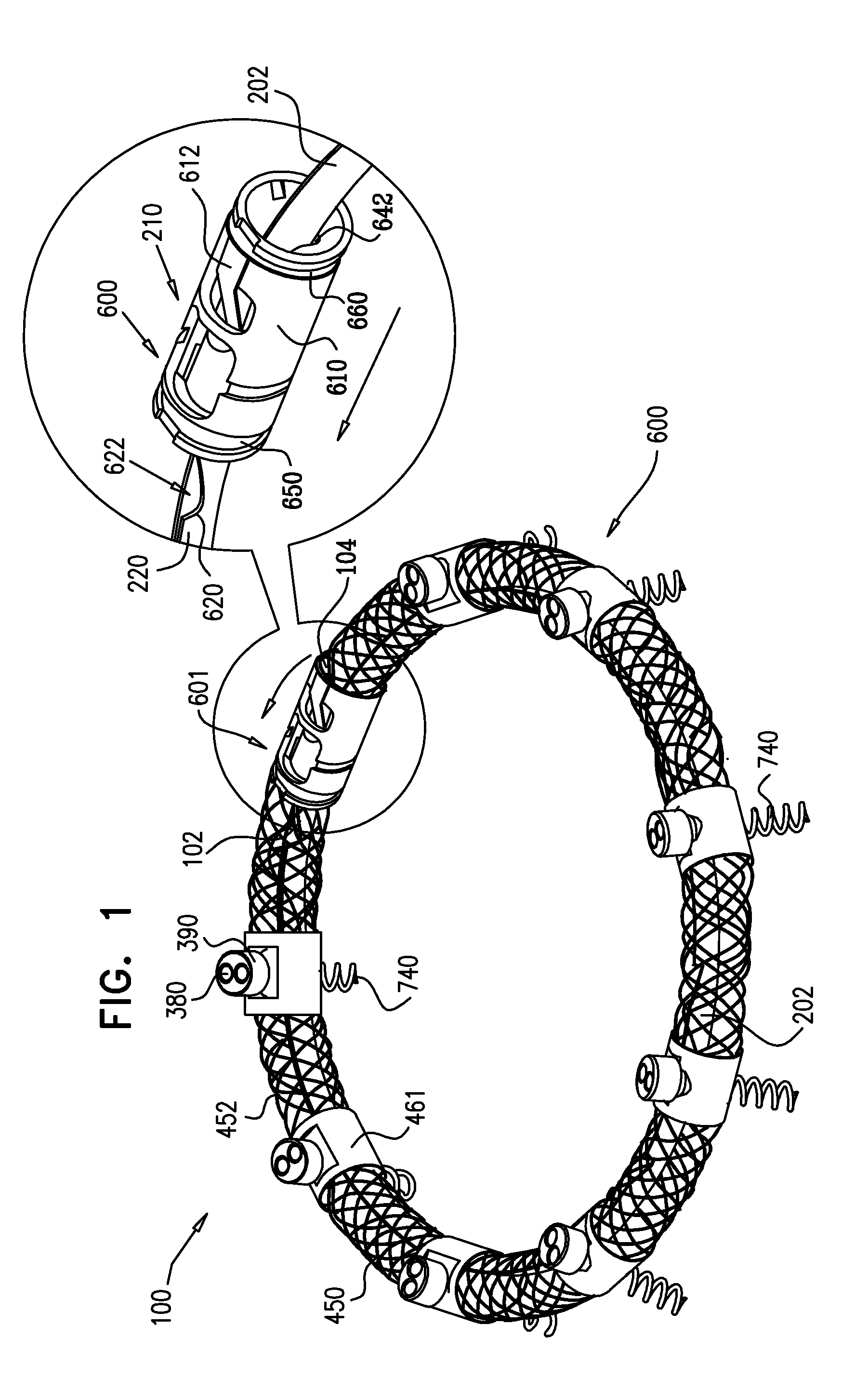
[0414]Reference is now made to FIG. 1, which is a schematic illustration of an annuloplasty structure 100, e.g., at least one elongate segment or tubular element, comprising a plurality of compressible subunits 450 and a plurality of anchor mounts 461, in accordance with an embodiment of the present invention. Structure 100 comprises a modular annuloplasty structure in which the plurality of compressible subunits 450 are alternately disposed with respect to the plurality of anchor mounts 461. Typically, structure 100 comprises an implant shaped to define a tubular structure having a cross-section of any suitable shape, e.g., circular or elliptical. Compressible subunits 450 are shaped to define a hollow lumen and comprise a braided mesh 452 (e.g., wire or polyester), by way of illustration and not limitation. For example, compressible subunits 450 may comprise a plurality of coils, braided structures, stent-shaped struts, or accordion- or bellows-shaped structures. A ratchet mechani...
PUM
Abstract
A method for performing an annuloplasty includes positioning an annuloplasty ring structure along an atrial surface of an annulus of a heart valve. While a distal portion of a tube is longitudinally advanced through a channel of the ring structure, it faces a first portion of tissue of the annulus. A first tissue anchor is anchored to the first portion of tissue, from within the channel, while the distal end of the tube faces the first portion of the tissue. After moving the distal portion of the tube to a second portion of the structure, the second portion of the structure is anchored to a second portion of tissue by anchoring a second tissue anchor to the second portion of the tissue while the distal end of the tube faces the second portion of the tissue. Other embodiments are also described.
Description
CROSS-REFERENCES TO RELATED APPLICATIONS[0001]The present application:[0002](a) is a continuation of U.S. patent application Ser. No. 12 / 996,954 to Gross et al., entitled, “Annuloplasty devices and methods of delivery therefor,” filed Mar. 24, 2011, which published as US 2011 / 0166649, and which is a US national phase application of PCT Patent Application PCT / IL2009 / 000593 to Gross et al., entitled, “Annuloplasty devices and methods of delivery therefor,” filed Jun. 15, 2009, which published as WO 10 / 004546, which claims priority from U.S. Provisional Patent Application 61 / 132,295 to Gross et al., entitled, “Annuloplasty devices and methods of delivery therefor,” filed Jun. 16, 2008; and[0003](b) is a continuation-in-part of U.S. patent application Ser. No. 11 / 950,930 to Gross et al., entitled, “Segmented ring placement,” filed Dec. 5, 2007, which published as US 2008 / 0262609, and which claims priority from:[0004](i) U.S. Provisional Patent Application 60 / 873,075 to Gross et al., ent...
Claims
Application Information
Patent Timeline
Application Date:The date an application was filed.
Publication Date:The date a patent or application was officially published.
First Publication Date:The earliest publication date of a patent with the same application number.
Issue Date:Publication date of the patent grant document.
PCT Entry Date:The Entry date of PCT National Phase.
Estimated Expiry Date:The statutory expiry date of a patent right according to the Patent Law, and it is the longest term of protection that the patent right can achieve without the termination of the patent right due to other reasons(Term extension factor has been taken into account ).
Invalid Date:Actual expiry date is based on effective date or publication date of legal transaction data of invalid patent.
Patent Type & AuthorityApplications(United States)

