Implantation of repair devices in the heart

Active Publication Date: 2019-11-07
VALTECH CARDIO LTD
View PDF0 Cites 12 Cited by
  • Summary
  • Abstract
  • Description
  • Claims
  • Application Information

AI Technical Summary

Benefits of technology

[0372]In an embodiment, the distance between the distal rotational subunits enables the distal rotational subunits to be corkscrewed around the bar and subsequently into the annulus of the patient

Problems solved by technology

Mitral regurgitation of blood from the left ventricle into the left atrium results in increased total stroke volume and decreased ca

Method used


Image

  • Implantation of repair devices in the heart
  • Implantation of repair devices in the heart
  • Implantation of repair devices in the heart

Examples


Embodiment Construction

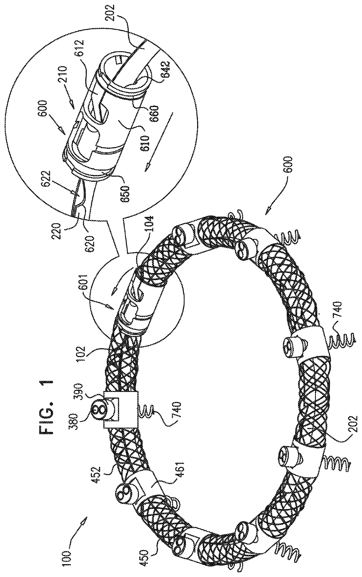
[0537]Reference is now made to FIG. 1, which is a schematic illustration of an annuloplasty structure 100, e.g., at least one elongate segment or tubular element, comprising a plurality of compressible subunits 450 and a plurality of anchor mounts 461, in accordance with an embodiment of the present invention. Structure 100 comprises a modular annuloplasty structure in which the plurality of compressible subunits 450 are alternately disposed with respect to the plurality of anchor mounts 461. Typically, structure 100 comprises an implant shaped to define a tubular structure having a cross-section of any suitable shape, e.g., circular or elliptical. Compressible subunits 450 are shaped to define a hollow lumen and comprise a braided mesh 452 (e.g., wire or polyester), by way of illustration and not limitation. For example, compressible subunits 450 may comprise a plurality of coils, braided structures, stent-shaped struts, or accordion- or bellows-shaped structures. A ratchet mechani...


PUM


Abstract

Apparatuses, systems, and devices usable for annuloplasty are provided. These can include an annuloplasty system comprising a segment having a lumen therethrough, the segment being positionable in a vicinity of a surface of a heart valve of a heart. The system can include a tube having a distal portion that is movable through the lumen of the segment and a distal end passable through an opening in the segment that is in fluid communication with the lumen. One or more tissue anchors are deliverable through the tube, the tissue anchor(s) being shaped so as to define a tissue coupling element. The distal portion of the tube can be removably positioned within the lumen of the segment, and, while so positioned, to deploy the tissue coupling element from the distal end of the tube in order to penetrate the tissue coupling element into cardiac tissue. Other embodiments are also described.

Description

CROSS-REFERENCES TO RELATED APPLICATIONS[0001]The present application is continuation of U.S. Ser. No. 15 / 983,542 to Gross et al., entitled, “Implantation of Repair Devices in the Heart,” filed May 18, 2018, which published as US 2018 / 0263776 and which is a continuation of U.S. Ser. No. 15 / 249,957 to Gross et al., entitled, “Implantation of Repair Devices in the Heart,” filed Aug. 29, 2016 (U.S. Pat. No. 9,974,653), which is a continuation of U.S. Ser. No. 15 / 144,127 to Gross et al., entitled, “Implant and anchor placement,” filed May 2, 2016 (U.S. Pat. No. 9,872,769), which is a continuation of U.S. patent application Ser. No. 14 / 551,951 to Gross et al., entitled, “Implant and anchor placement,” filed Nov. 24, 2014 (U.S. Pat. No. 9,351,830), and which:[0002](a) is a continuation of U.S. patent application Ser. No. 12 / 996,954 to Gross et al., entitled, “Annuloplasty devices and methods of delivery therefor,” filed Mar. 24, 2011, which published as US 2011 / 0166649, which issued as U....

Claims


Application Information

Patent Timeline
IPC IPC(8): A61F2/24A61B17/064
CPCA61F2/2466A61B2017/00407A61B17/064A61F2/2445A61B2017/0649A61F2/2448A61B2017/0647
Inventor GROSS, AMIRBEINART, IFTAHMILLER, ERANCABIRI, OZELIACHAR, ELIAHULILACH, NIRGROSSFELD, RAMGOLOM, DMITRYMEYER-BRODNITZ, GIDEONMOSAIUF, ARNON
Owner VALTECH CARDIO LTD
Why Eureka
Try Eureka