Image capturing apparatus and image capturing method

a technology of image capturing and image capturing, which is applied in the direction of color television details, television system details, television systems, etc., can solve the problems of object tracking that does not function correctly, interfere with the object tracking, etc., and achieve the effect of suppressing the amount of movement of the predetermined obj

Active Publication Date: 2015-03-26
CANON KK
View PDF2 Cites 8 Cited by
  • Summary
  • Abstract
  • Description
  • Claims
  • Application Information

AI Technical Summary

Benefits of technology

[0011]According to an aspect of the present invention, there is provided an image capturing apparatus comprising: an object detection unit configured to detect a predetermined object in a captured image that is captured by an image sensor; a movement amount acquisition unit configured to acquire an amount of movement of the predetermined object that moves in an image capturing screen, from two captured images that are captured by the image sensor; an object tracking unit configured to suppress the amount of movement of the predetermined object in the image capturing screen, by moving an optical element in a direction that is different from a direction of an optical axis of an image capturing optical system that guides a light beam toward the image sensor, the optical element constituting the image capturing optical system; a motion vector detection unit configured to compare two captured images that are captured by the image sensor and detect a motion vector indicating an image blur amount; an image blur correction unit configured to correct image blur, based on the motion vector; and a switching unit configured to switch whether or not to perform object tracking using the object tracking unit, wherein the image blur correction unit makes effect of the image blur correction in a case of performing the object tracking smaller than effect of the image blur correction in a case of not performing the object tracking.
[0012]According to another aspect of the present invention, there is provided an image capturing method comprising: an object detection step of detecting a predetermined object in a captured image that is captured by an image sensor; a movement amount acquisition step of acquiring an amount of movement of the predetermined object that moves in an image capturing screen, from two captured images that are captured by the image sensor; an object tracking step of suppressing the amount of movement of the predetermined object in the image capturing screen, by moving an optical element in a direction that is different from a direction of an optical axis of an image capturing optical system that guides a light beam toward the image sensor, the optical element constituting the image capturing optical system; a motion vector detection step of comparing two captured images that are captured by the image sensor and detecting a motion vector indicating an image blur amount; an image blur correction step of correcting image blur, based on the motion vector; and a switching step of switching whether or not to perform object tracking in the object tracking step, wherein in the image blur correction step, effect of the image blur correction in a case of performing the object tracking is made smaller than effect of the image blur correction in a case of not performing the object tracking.

Problems solved by technology

If the electronic blur correction based on this motion vector is performed, the object tracking does not function correctly.
If this electronic blur correction function changes the position of the image memory from which the captured image is read out, based on the representative vector detected as a result of the background position changing when object tracking is performed using the correction lens as mentioned above, it may possibly interfere with the object tracking.

Method used


Image

  • Image capturing apparatus and image capturing method
  • Image capturing apparatus and image capturing method
  • Image capturing apparatus and image capturing method

Examples


first embodiment

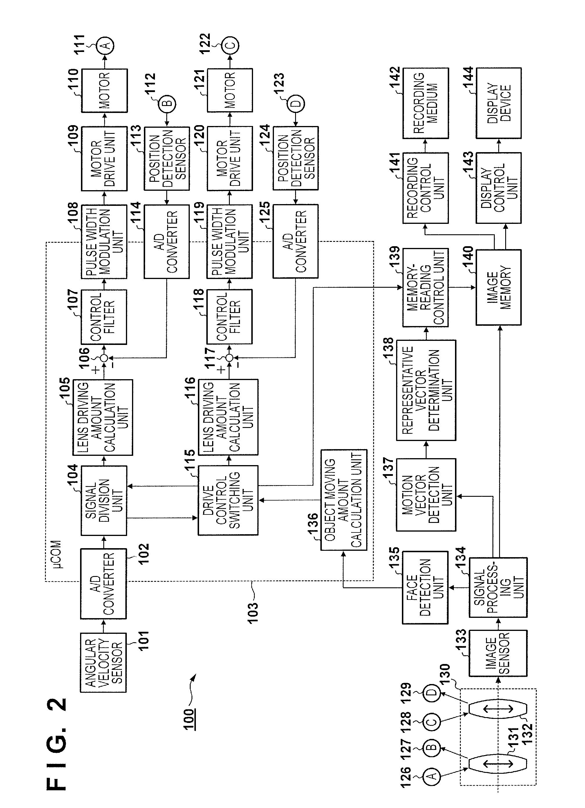
[0028]An embodiment of the present invention will be described. FIG. 2 is a block diagram showing a configuration of an image capturing apparatus 100 according to the first embodiment. Each constituent unit of the image capturing apparatus 100 in FIG. 2 and exemplary operations thereof will now be specifically described.

[0029]The image capturing apparatus 100 has two correction lenses (image blur correction lenses), namely a correction lens 131 and a correction lens 132 that are able to vertically move with respect to the optical axis of an image capturing optical system, and uses the correction lens 131 to perform optical blur correction. The image capturing apparatus 100 can select a blur correction mode or an object tracking mode as a control mode for the correction lens 131. In the case of the blur correction mode, the image capturing apparatus 100 uses the correction lens 132 to perform optical blur correction control. In the case of the object tracking mode, the image capturin...

second embodiment

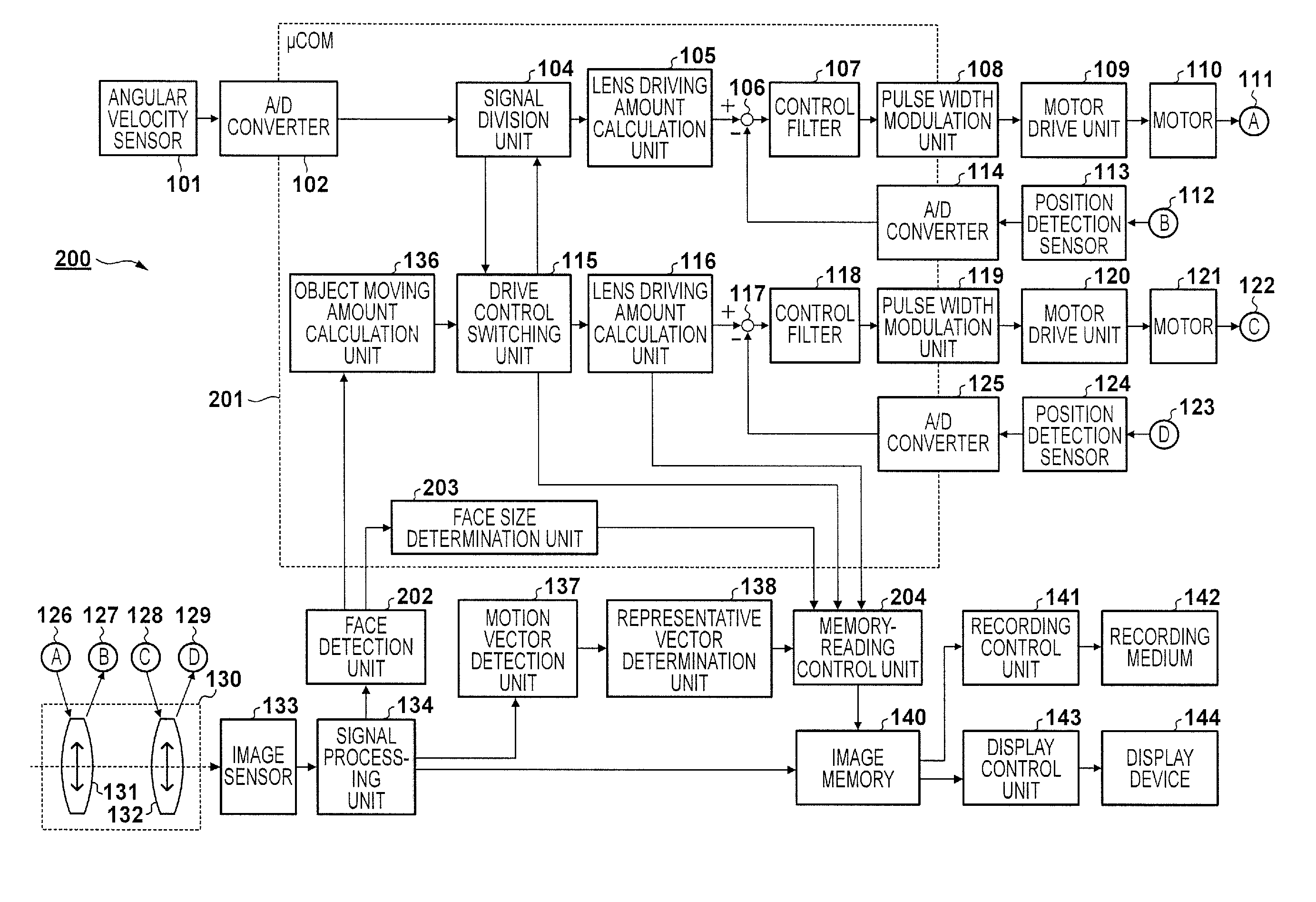
[0059]FIG. 4 is a block diagram showing a configuration of an image capturing apparatus 200 according to the second embodiment. In FIG. 4, the same configuration as that in FIG. 2 will be given the same reference numeral, and the description thereof will be omitted. In the first embodiment, in the case of the object tracking mode, the image capturing apparatus 100 reduces or nullifies the effect of the electronic blur correction. In contrast, in the second embodiment, the image capturing apparatus 200 performs correction processing using the representative vector in the case of the object tracking mode as well. However, although the details will be described later, this correction processing is similar to the electronic blur correction in the first embodiment in that the position of the image memory 140 from which the captured image is read out is changed, while the correction processing in the second embodiment has a function of improving object tracking accuracy, rather than corre...

third embodiment

[0069]FIG. 7 is a block diagram showing a configuration of an image capturing apparatus 300 according to the third embodiment. In FIG. 7, the same configuration as that in FIG. 2 will be given the same reference numeral, and the description thereof will be omitted. The image capturing apparatus 300 realizes the electronic tracking correction using a different method from that of the image capturing apparatus 200 in the second embodiment.

[0070]In the image capturing apparatus 300 shown in FIG. 7, a μCOM 301 includes a motion vector detection area calculation unit 302. FIG. 8 is a flowchart showing electronic tracking correction processing executed by the image capturing apparatus 300. This flowchart replaces step S107 in FIG. 3.

[0071]In step S300, the face detection unit 135 detects a face region, and notifies the motion vector detection area calculation unit 302 of information of the detected face region. In step S301, the motion vector detection area calculation unit 302 calculates...


PUM


Abstract

An image capturing apparatus comprises an object detection unit configured to detect a predetermined object and a movement amount acquisition unit configured to acquire an amount of movement of the predetermined object. An object tracking unit suppresses the amount of movement of the predetermined object by moving an optical element constituting an image capturing optical system. A motion vector detection unit detects a motion vector indicating an image blur amount. An image blur correction unit corrects image blur based on the motion vector. A switching unit switches whether or not to perform object tracking using the object tracking unit. The image blur correction unit makes effect of the image blur correction in a case of performing the object tracking smaller than effect of the image blur correction in a case of not performing the object tracking.

Description

BACKGROUND OF THE INVENTION[0001]1. Field of the Invention[0002]The present invention relates to an image capturing apparatus and an image capturing method.[0003]2. Description of the Related Art[0004]In recent years, various functions for assisting shooting in an image capturing apparatus, such as a digital video camera, have been proposed. For example, blur correction functions are installed in many image capturing apparatuses, and are classified into optical blur correction and electronic blur correction, depending on the correction method. The optical blur correction is a method in which a shake of an image capturing apparatus is detected, and a change of the optical axis due to the shake is cancelled by displacing a correction lens, which is part of an image capturing optical system, based on the detected shake. The electronic blur correction is a method in which a shake of an image capturing apparatus is detected using a motion vector in a captured image, and when an image for...

Claims


Application Information

Patent Timeline
Patent Type & Authority Applications(United States)
IPC IPC(8): H04N5/232
CPCH04N5/23245H04N5/23267H04N5/23254H04N23/611H04N23/6811H04N23/683H04N23/667H04N23/687
Inventor SUGAYA, TOMOHIRO
Owner CANON KK
Why Eureka
Try Eureka