

High-frequency signal line and manufacturing method thereof
- Summary
- Abstract
- Description
- Claims
- Application Information
AI Technical Summary
Benefits of technology
Problems solved by technology
Method used
Image

Examples
first modification
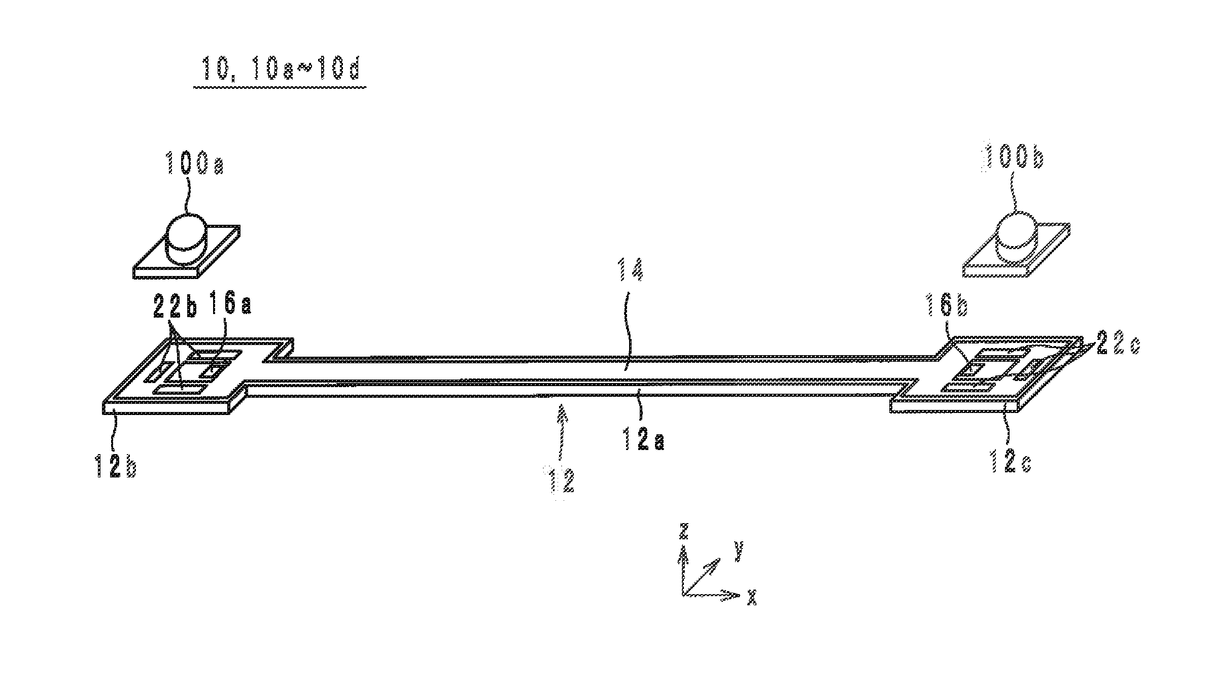
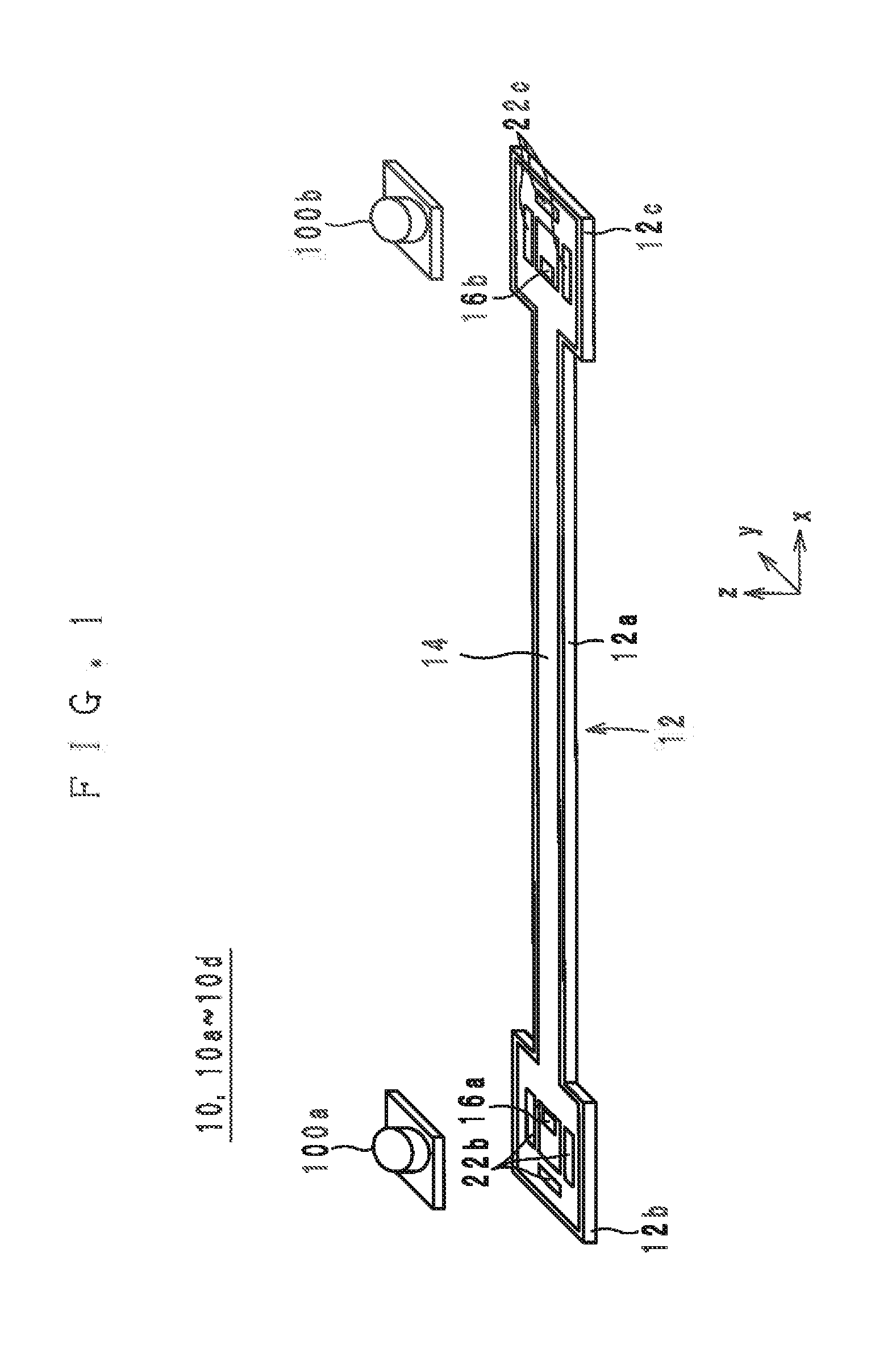
[0109]A high-frequency signal line 10a according to a first modification of a preferred embodiment of the present invention is hereinafter described with reference to the drawings. FIG. 15 is a sectional view of the line portion 12a of the high-frequency signal line 10a cut at a bridge 60. FIG. 16 is a sectional view of the line portion 12a of the high-frequency signal line 10a cut at an opening 30. The appearance of the high-frequency signal line 10a is as illustrated in FIG. 1.
[0110]The high-frequency signal line 10a is different from the high-frequency signal line 10 in that instead of the protective layer 14, a dielectric sheet 18d is placed on the positive side in the z-direction of the dielectric sheet 18a. Accordingly, the main ground conductor 22 is covered by the dielectric sheet 18d.
[0111]Next, a non-limiting example of a manufacturing method of the high-frequency signal line 10a is described. The following description of the manufacturing method of the high-frequency sig...
second preferred embodiment
[0115]A high-frequency signal line 10b according to a second modification of a preferred embodiment of the present invention is hereinafter described with reference to the drawings. FIG. 19 is an exploded view of the dielectric body 12 of the high-frequency signal line 10b according to the second modification. FIG. 20 is a sectional view of the line portion 12a of the high-frequency signal line 10b cut at a bridge 60. FIG. 21 is a sectional view of the line portion 12a of the high-frequency signal line 10b cut at an opening 30. The appearance of the high-frequency signal line 10b is as illustrated in FIG. 1.
[0116]As seen in FIGS. 19 through 21, the high-frequency signal line 10b is different from the high-frequency signal line 10a in that the insulators 60a and 60b are not provided. In the high-frequency signal line 10b, as seen in FIGS. 20 and 21, the protective layer 14 is provided inside the grooves G1 and G2.
[0117]Next, a non-limiting example of a manufacturing method of the hig...
third modification
[0123]A high-frequency signal line 10c according to a third preferred embodiment of a preferred embodiment of the present invention and a manufacturing method thereof are hereinafter described with reference to the drawings. FIG. 26 is an exploded view of the high-frequency signal line 10c according to the third modification. The appearance of the high-frequency signal line 10c is as illustrated in FIG. 1.
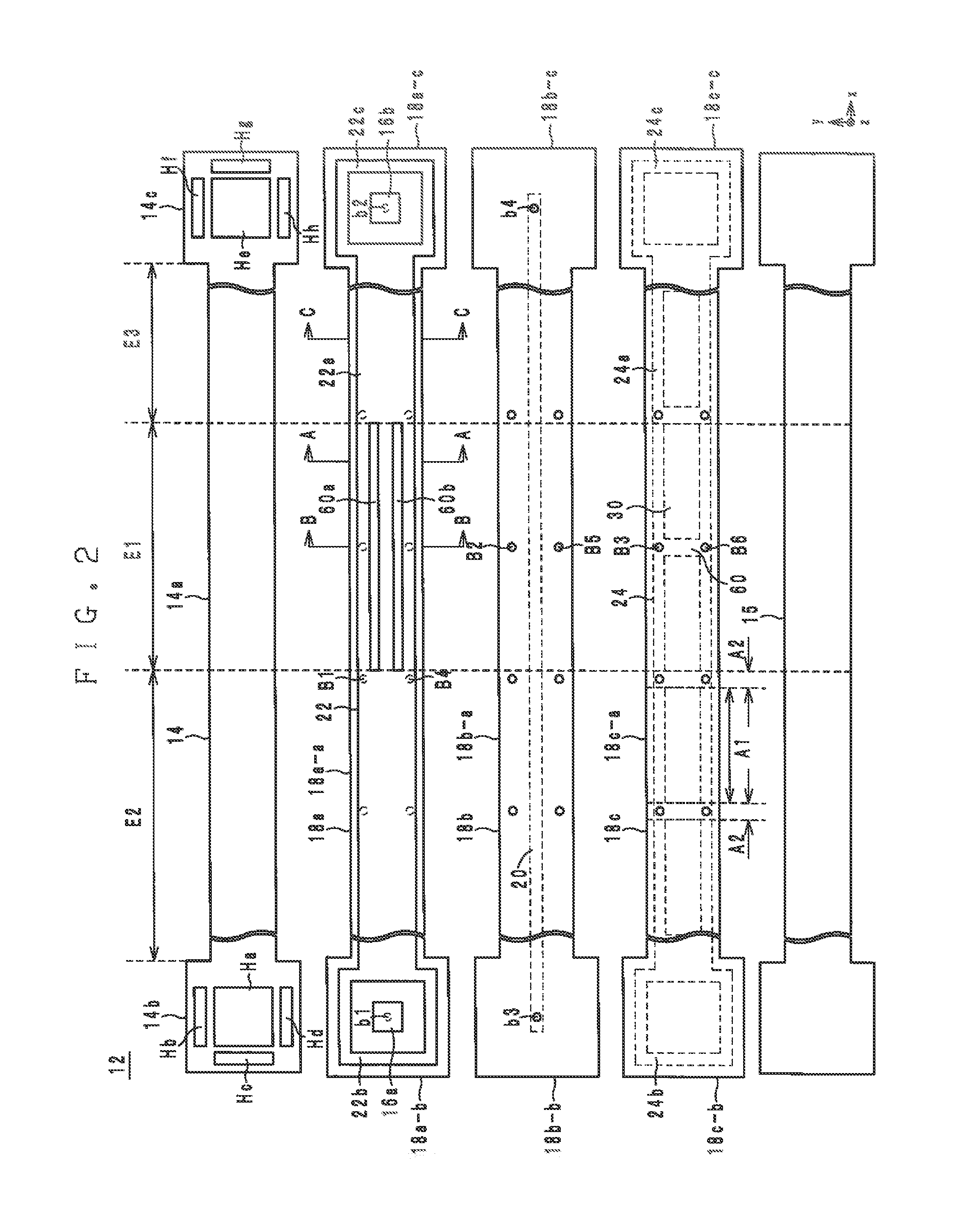
[0124]As seen in FIG. 26, the high-frequency signal line 10c is different from the high-frequency signal line 10b in that reinforcement ground conductors 40 and 42 are further provided. More specifically, the reinforcement ground conductor 40 is provided on the lower surface of the dielectric sheet 18b in the section E1 so as to extend in the x-direction. When viewed from the z-direction, the reinforcement ground conductor 40 is located farther in the positive y-direction than the signal line 20 and overlaps with the auxiliary ground conductor 24 while not lapping over the openings...
PUM
| Property | Measurement | Unit |
|---|---|---|
| Flexibility | aaaaa | aaaaa |
| Frequency | aaaaa | aaaaa |
Abstract
Description
Claims
Application Information