Sample Holder with Magnetic Base and Magnetisable Body

a magnetic base and sample holder technology, applied in the direction of filtration separation, instruments, separation processes, etc., can solve the problems of mechanical clips being subject to wear, non-optimal separation, and adding to the complexity of the process

Active Publication Date: 2015-04-02
LIFE TECH AS
View PDF7 Cites 15 Cited by
  • Summary
  • Abstract
  • Description
  • Claims
  • Application Information

AI Technical Summary

Benefits of technology

[0011]In a third aspect the invention provides use of a sample holder of the invention, when the body is seated on the base

Problems solved by technology

A variant designed to work with 96 well microplates utilizes adjustable clips to hold the microplate in place, however this requires the user to manually adjust the clips to ensure that the microplate is retained the optimal sep

Method used


Image

  • Sample Holder with Magnetic Base and Magnetisable Body
  • Sample Holder with Magnetic Base and Magnetisable Body
  • Sample Holder with Magnetic Base and Magnetisable Body

Examples


example 1

nt of Magnetic Separation Efficiency

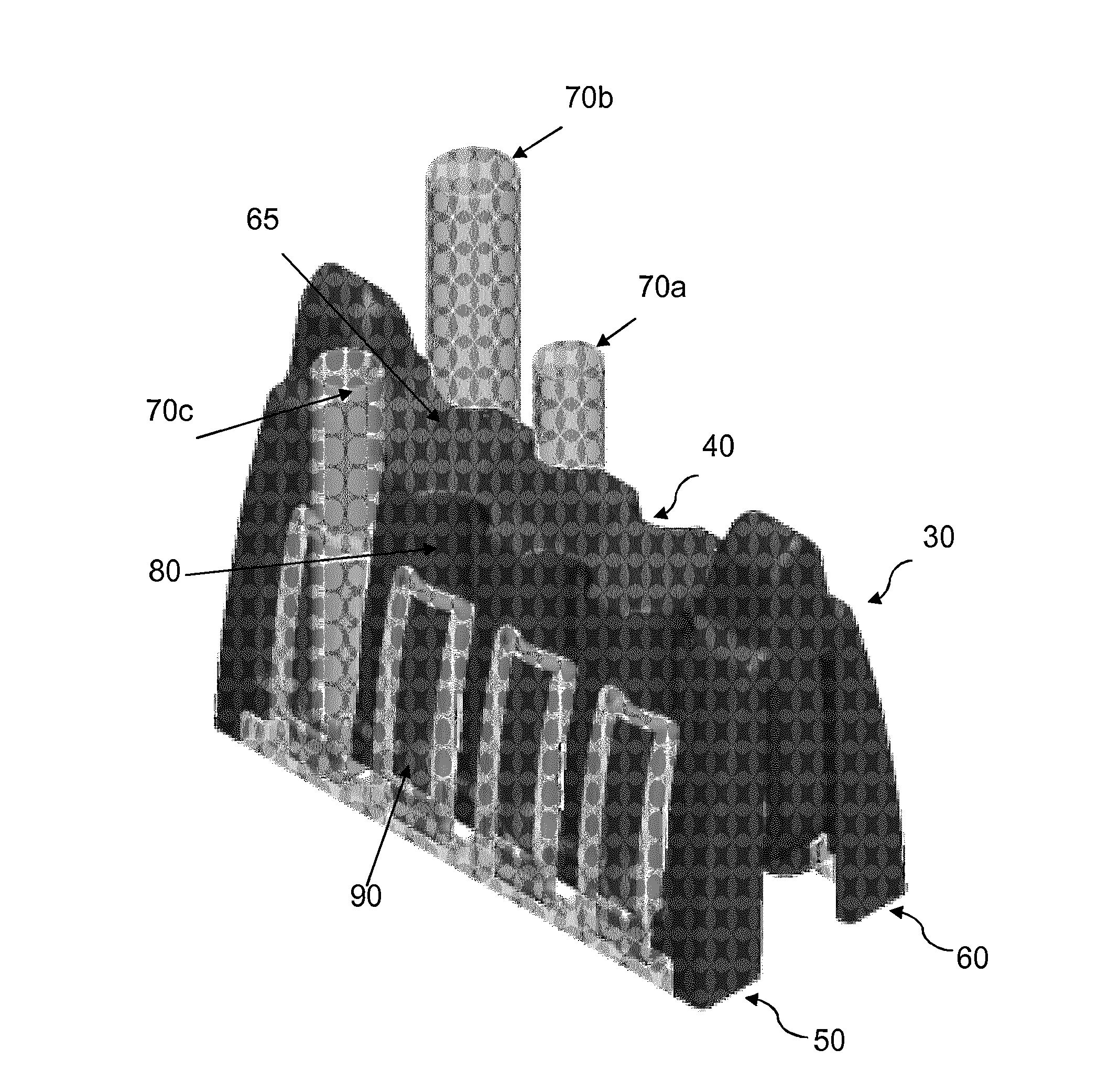
[0061]Measurements with a gauss meter indicated that, in the region of the sample vessel retaining portion 40 proximate (e.g. + / −1 to 3 mm) to the plane of the magnetisable member 100, the magnetisable member 100 caused a reduction in the magnetic field strength. The experiment of Example 1 was therefore conducted to determine the effect, if any, of this decrease in magnetic field strength on the magnetic separation efficiency of the sample rack.

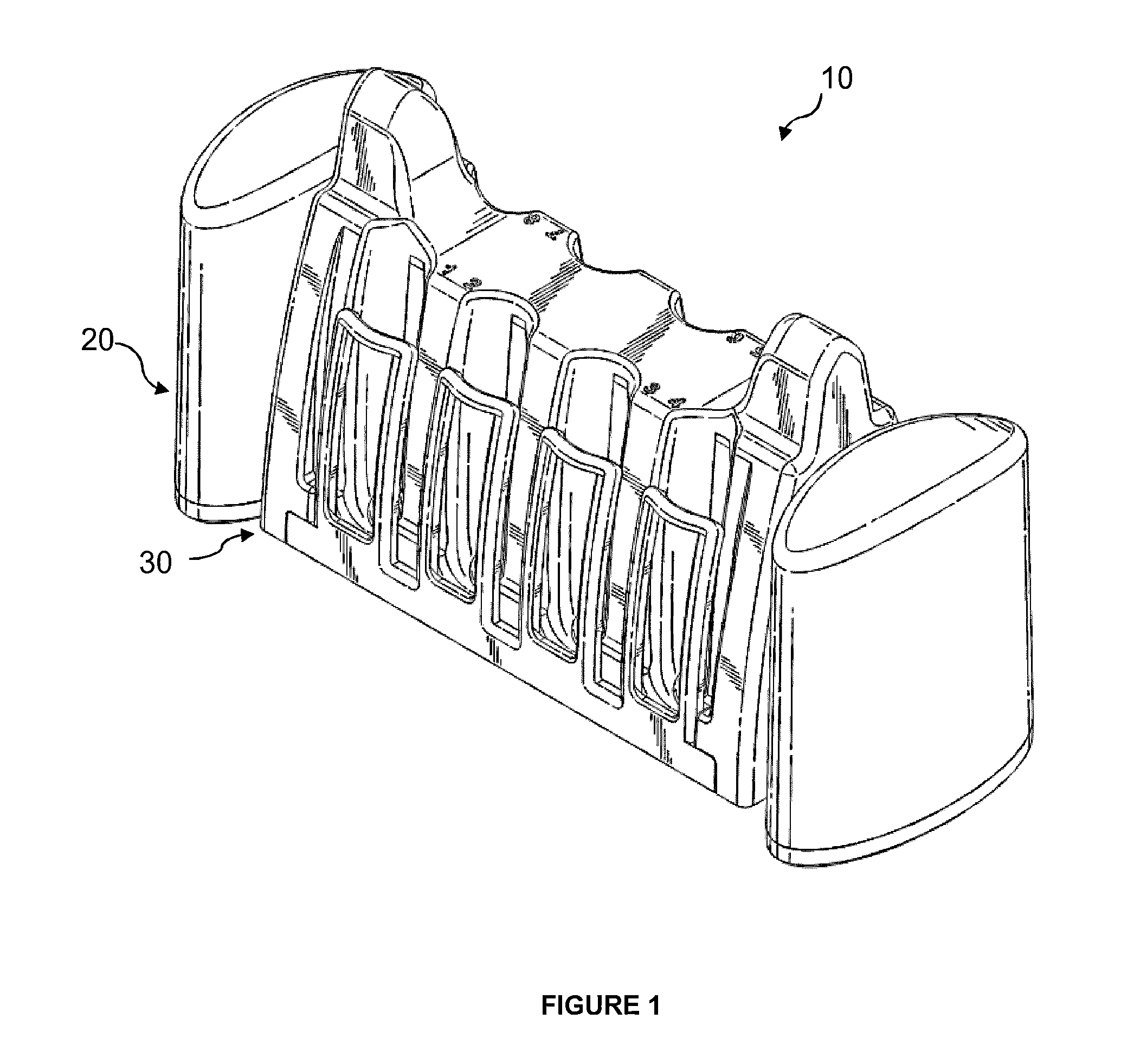
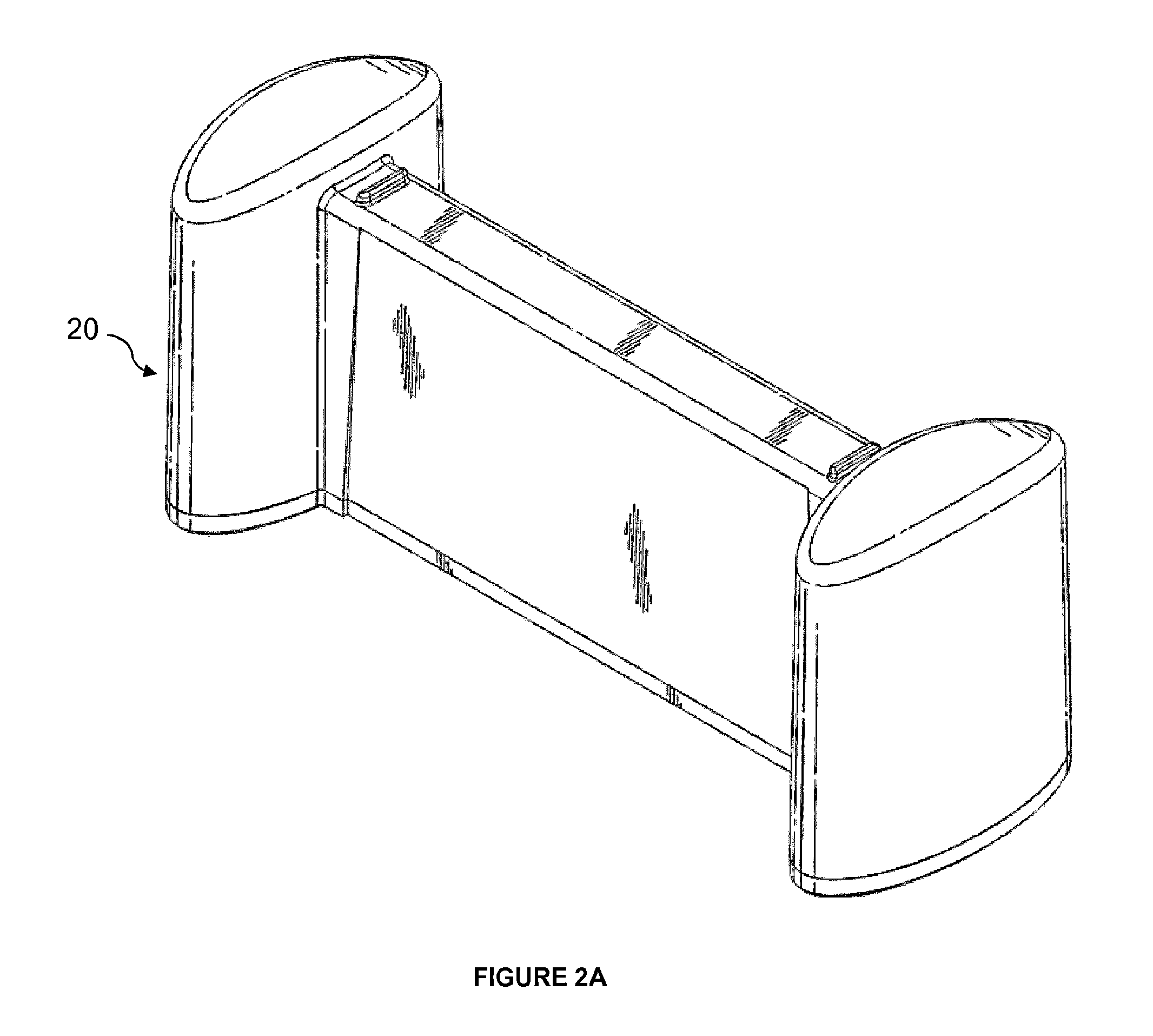
[0062]Magnetic separation efficiency was measured determined with a sample holder of FIG. 1, when the sample rack 30 (sample rack A) was fitted to the base 20. The magnetisable member 100 was a metal plate. Comparative measurements were performed with an equivalent base and non-magnetic sample rack (sample rack B). The non-magnetic sample rack differed from sample rack 30 in that it did not have a magnetisable member.

[0063]The assessment of magnetic separation was perfomed with Dynabeads® MyOne magnetic be...


PUM

PropertyMeasurementUnit
Diameteraaaaaaaaaa
Diameteraaaaaaaaaa
Diameteraaaaaaaaaa

Abstract

This invention relates to a sample holder for isolating magnetically labelled particles from a non-magnetic medium in a plurality of samples. The holder comprises a magnetic base for applying a magnetic force to the magnetically labelled particles and a body which is mountable on the base and demountable therefrom. The body comprises an array of sample holding portions and a magnetisable member which is magnetically urged towards the magnetic base when the body is seated on the base, whereby the body is urged to remain seated on the base. The invention also relates to use of the sample holder to separate magnetic particles from a non-magnetic medium and methods of performing such a separation.

Description

[0001]This invention relates to a sample holder for isolating magnetically labelled particles from a non-magnetic medium. The sample holder has a body and a magnetic base. The invention also relates to the body and magnetic base and use of the body and magnetic base in methods of isolating magnetically labeled particles from non-magnetic media.BACKGROUND[0002]The use of a high-gradient magnetic field to separate magnetically attractable particles from a fluid in which they are suspended is well known. Moreover, magnetic separation devices are used in a variety of industries including pharmaceutical, medical, agricultural, scientific and engineering fields. For example in biotechnology, a high-gradient magnetic field may be used to separate magnetically labelled bone marrow cells from a blood sample.[0003]WO 90 / 14891 DYNAL A.S. discloses a conventional magnetic separation device whereby a test-tube / sample vessel, containing a fluid in which magnetically labelled particles are suspend...

Claims


Application Information

Patent Timeline
IPC IPC(8): B03C1/14
CPCB03C2201/18B03C1/14B01L9/06G01N35/0098B03C1/0332B03C1/0335B03C1/288B03C2201/26B03C1/002B03C1/025
Inventor NOKLEBY, LARSREED, BERITHILDISCH, TINENEURAUTER, AXL
Owner LIFE TECH AS
Why Eureka
Try Eureka