Anchored mounting ring

a mounting ring and anchoring technology, applied in the direction of prosthesis, therapy, heart stimulators, etc., can solve the problem that the installation procedure of the anchoring ring takes considerable tim

Inactive Publication Date: 2015-04-23
HEARTWARE INC
View PDF9 Cites 48 Cited by
  • Summary
  • Abstract
  • Description
  • Claims
  • Application Information

AI Technical Summary

Benefits of technology

[0010]In some embodiments, a mounting ring kit may include a tool for moving the anchors from the first position to the second position and may be adapted to simultaneously move more than one of the anchors. The plate may provide a mount for securing a device penetrating a wall of the heart.
[0011]A mounting ring according to one aspect of the disclosure may include a plate having an opening and a plurality of passageways; a plurality of anchors, each of which are pivotably connected to the plate to rotate about an axis tangent to a circle encircling the opening; and an annular wall adapted to be attached to the plate. The annular wall may be shaped to be positioned within the opening, attached to the plate, and locked to the plate by a bayonet lock. The anchors may include a hook, pin, screw, or any combination thereof. The anchors may extend away from the proximal side of the plate in a first position and extend from the distal side of the passageways in a second position to secure the distal side of the plate to the heart. Th...

Problems solved by technology

Suturing the mounting ring to the heart takes ...

Method used


Image

  • Anchored mounting ring
  • Anchored mounting ring
  • Anchored mounting ring

Examples


Embodiment Construction

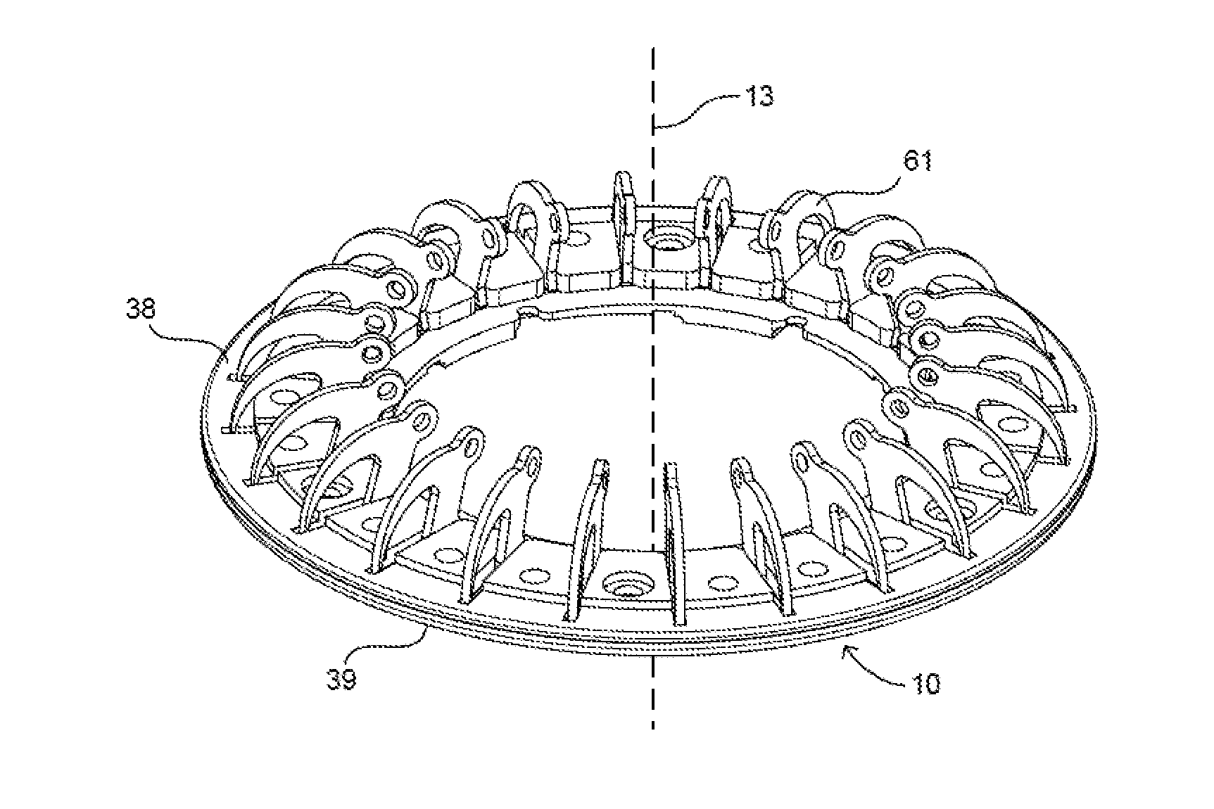
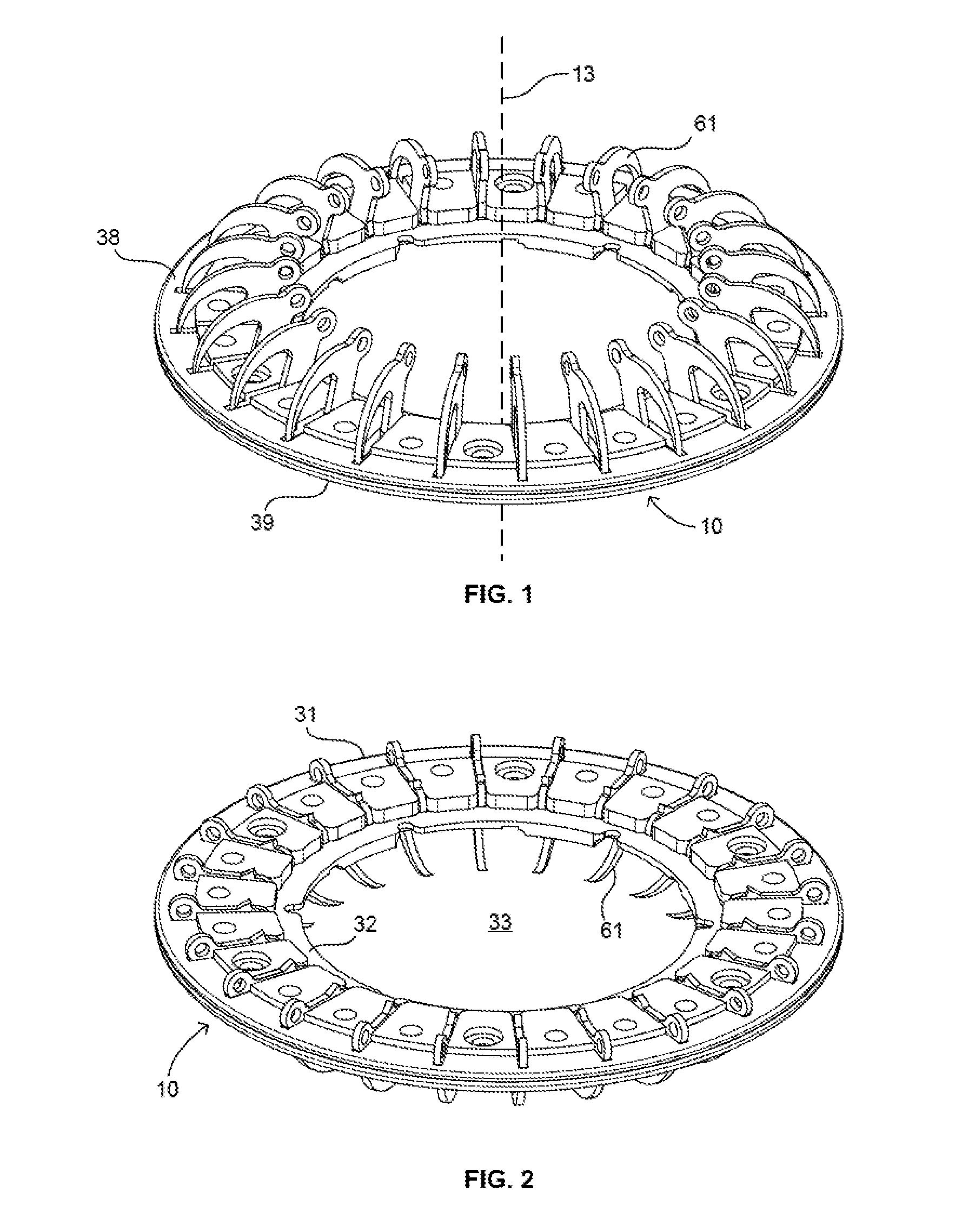
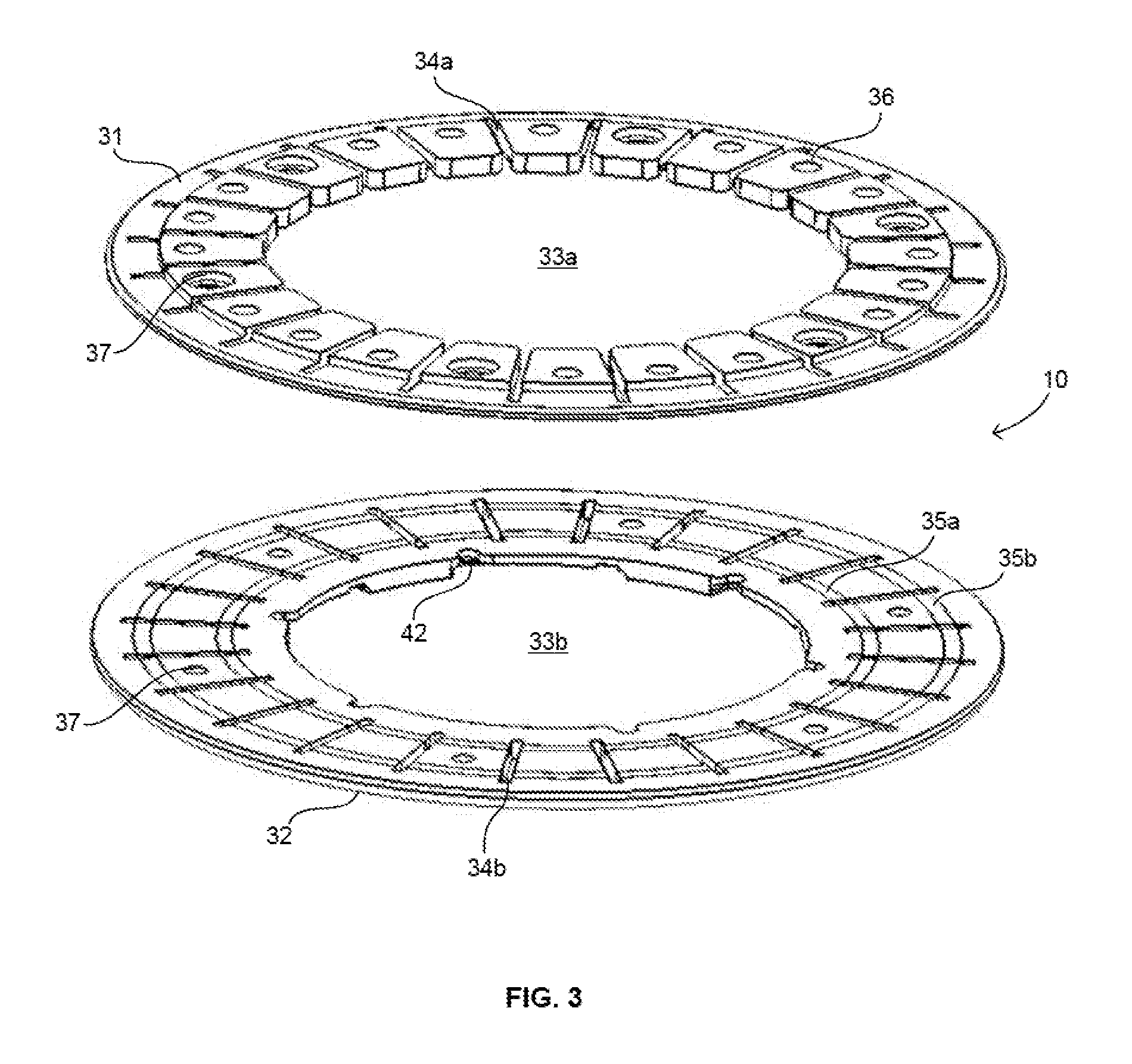
[0040]A mounting ring according to one embodiment of the invention includes a plate 10 (FIG. 1) having a proximal surface 38 and a distal surface 39. Plate 10 is generally in the form of a disc having a central 192 axis extending in the proximal to distal direction. As best seen in FIG. 3, the plate 10 includes a first piece 31 defining the proximal surface and a second piece 32 defining the distal surface. The first piece 31 has passageways 34a and second piece 32 has corresponding passageways 34b. The passageways 34a and 34b of the first piece 31 and second piece 32 are generally aligned with one another to provide a plurality of passageways 34 (FIGS. 1 and 2) extending completely through the plate 10 when the first piece 31 and second piece 32 are joined together. Passageways 34a and 34b are narrow, elongated slots extending radially with respect to the central axis 192. Merely by way of example, the width Wp of each passageway may be about 0.024 inches. The plate is preferably m...


PUM


Abstract

A mounting ring for a ventricular assist device or other device used in the heart includes a plate adapted to be secured to the exterior of the heart by rigid anchors such as hook, pin, or screw. When hooks are used, they can be pivotally mounted to the plate so that the hooks can rotate from retracted positions to advanced positions. A tool can be included in a mounting ring kit to move the hooks from their retracted positions to their advanced positions so that the hooks secure the plate to the heart. Preferably, all of the hooks are advanced simultaneously. The VAD or other device is then secured to the plate. The plate can be mounted to the heart in less time than required to install a traditional mounting ring by suturing to the heart.

Description

CROSS-REFERENCE TO RELATED APPLICATIONS[0001]This application claims the benefit of the filing date of U.S. Provisional Patent Application No. 61 / 894,117, filed Oct. 22, 2013, the disclosure of which is hereby incorporated by reference herein.BACKGROUND OF THE INVENTION[0002]The present invention relates to components and methods used for mounting devices such as ventricular assist devices and associated elements to the heart of a living subject.[0003]The heart is sometimes incapable of providing sufficient pumping capacity to meet the needs of the body. The effects of this inadequacy can be alleviated by providing a mechanical pump referred to as a ventricular assist device (“VAD”) to supplement the pumping action of the heart. It is preferable for a VAD to have the ability to be implanted in a patient to supplement or replace the pumping action of the heart for an extended period of time. A patient may have a VAD for years while awaiting a suitable donor for a heart transplant.[00...

Claims


Application Information

Patent Timeline
IPC IPC(8): A61M1/10A61M1/12A61M60/178A61M60/863A61M60/865
CPCA61M1/1008A61M2210/125A61M2205/04A61M1/122A61B2017/3425A61B2017/3488A61M60/148A61M60/865A61M60/863A61M60/178
Inventor ANDRUS, LANCE LYNN
Owner HEARTWARE INC
Why Eureka
Try Eureka