
Method and apparatus for optimizing germicidal lamp performance in a disinfection device
a disinfection device and germicidal lamp technology, applied in the direction of material analysis, instruments, and treatment using wave/particle radiation, etc., can solve the problems of high risk of overheating and even melting of malgam spots
- Summary
- Abstract
- Description
- Claims
- Application Information
AI Technical Summary
Benefits of technology
Problems solved by technology
Method used
Image

Examples
Embodiment Construction
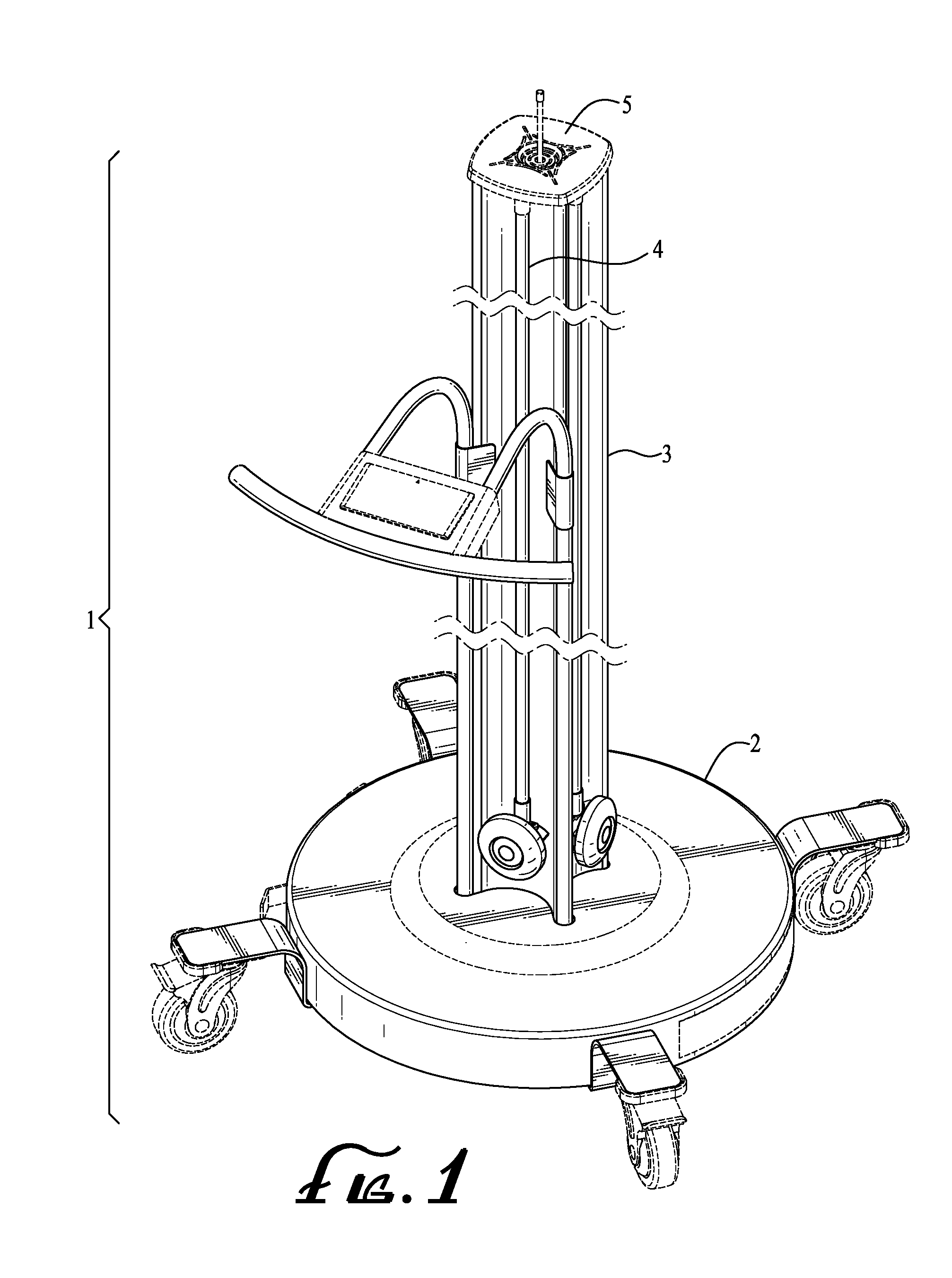
[0036]Referring to FIG. 1, a typical device 1 for the UV disinfection of air or surfaces is shown. The basic elements of the device are a base 2, a support, in this case, acting also as a conduit 3 and an opening 5 for the exit of air. One or more lamps 4 are installed around the support or conduit 3.
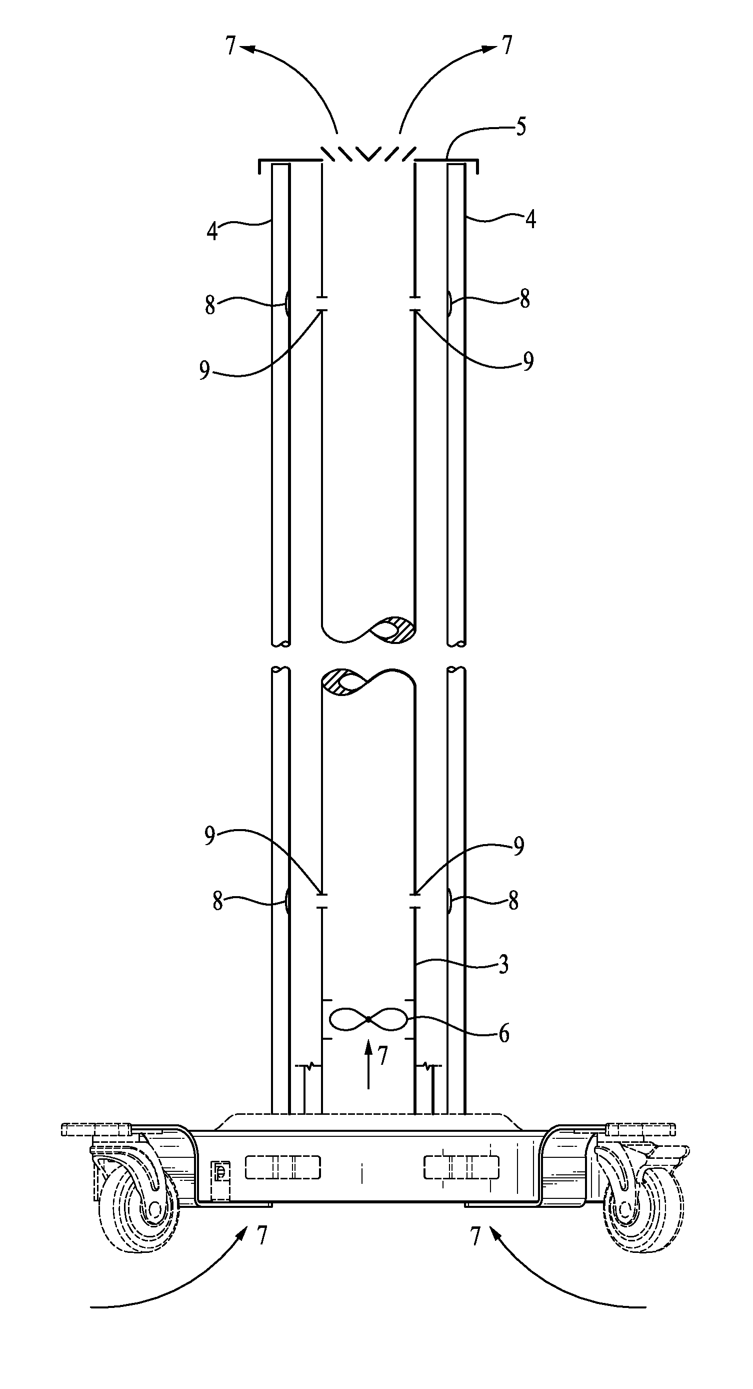
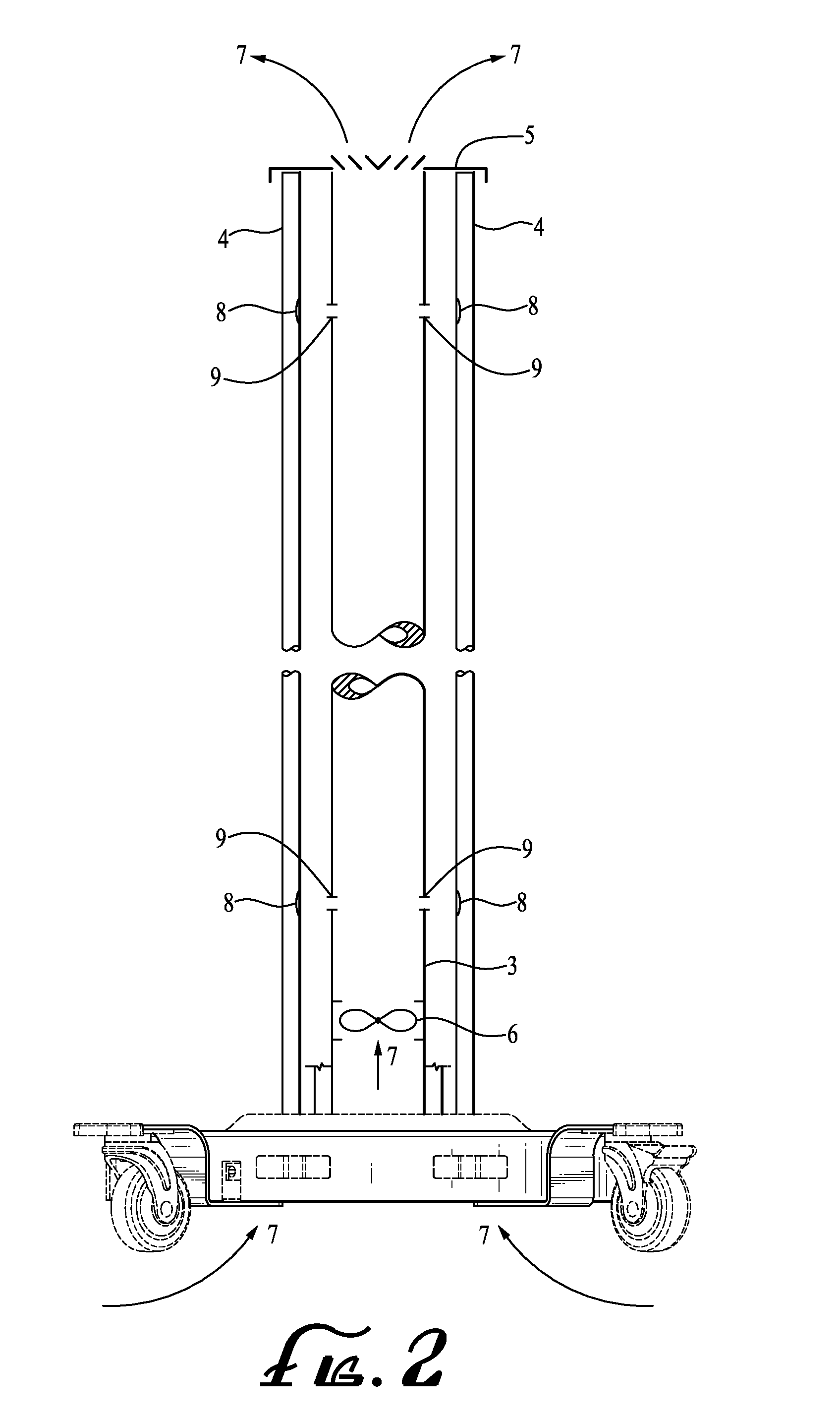
[0037]FIG. 2 shows the typical device 1, in cross section. An air moving device 6, including without limitation a fan or blower, is installed in the conduit 6 or may be installed in the base 2. The air moving device 6 causes air 7 to move into the conduit 3 and much of the air to exit through opening 5. Orifices, openings or holes 9 of a specific pre-determined diameter are placed in the conduit 4 at a strategic point selected to direct the air 7 through the orifices 9 to an area near or at the critical spot or points 8 (including mercury spot or amalgam spot, which contains mercury) on the lamp 4.
[0038]In another embodiment, not shown, the opening 5 may be omitted allowing all the air ...
PUM
| Property | Measurement | Unit |
|---|---|---|
| spectral wavelength | aaaaa | aaaaa |
| UVC wavelength | aaaaa | aaaaa |
| temperature | aaaaa | aaaaa |
Abstract
Description
Claims
Application Information