Sputum Apparatus, Artificial Ventilation System, and Method for Operating Sputum Apparatus

a technology of artificial ventilation and sputum, which is applied in the direction of valve operating means/release devices, applications, diagnostic recording/measuring, etc., can solve the problems of troublesome sputum operation and a great burden of work, and achieve the effect of automatic aspiration of sputum safely

Active Publication Date: 2015-07-09
ULVAC KIKO +1
View PDF15 Cites 8 Cited by
  • Summary
  • Abstract
  • Description
  • Claims
  • Application Information

AI Technical Summary

Benefits of technology

[0007]In view of the circumstances as described above, an object of the present invention is to provide a sputum apparatus capable of automatically aspirating sputum safely.

Problems solved by technology

Such an operation for sputum is troublesome; this operation needs to be performed night and day; and nurses, caregivers, and others should bear a great burden of work.

Method used


Image

  • Sputum Apparatus, Artificial Ventilation System, and Method for Operating Sputum Apparatus
  • Sputum Apparatus, Artificial Ventilation System, and Method for Operating Sputum Apparatus
  • Sputum Apparatus, Artificial Ventilation System, and Method for Operating Sputum Apparatus

Examples


first embodiment

Artificial Ventilation System

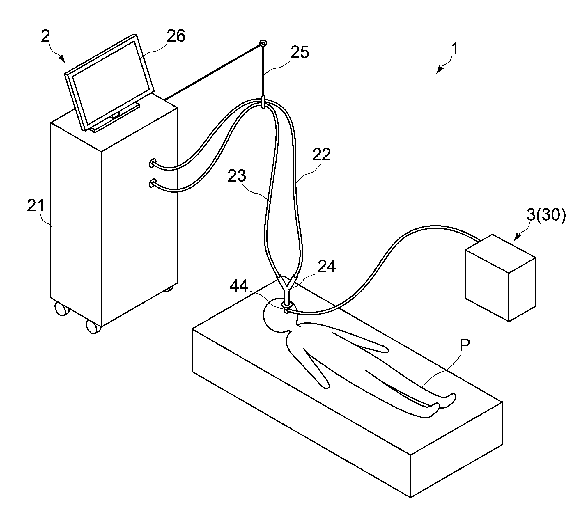
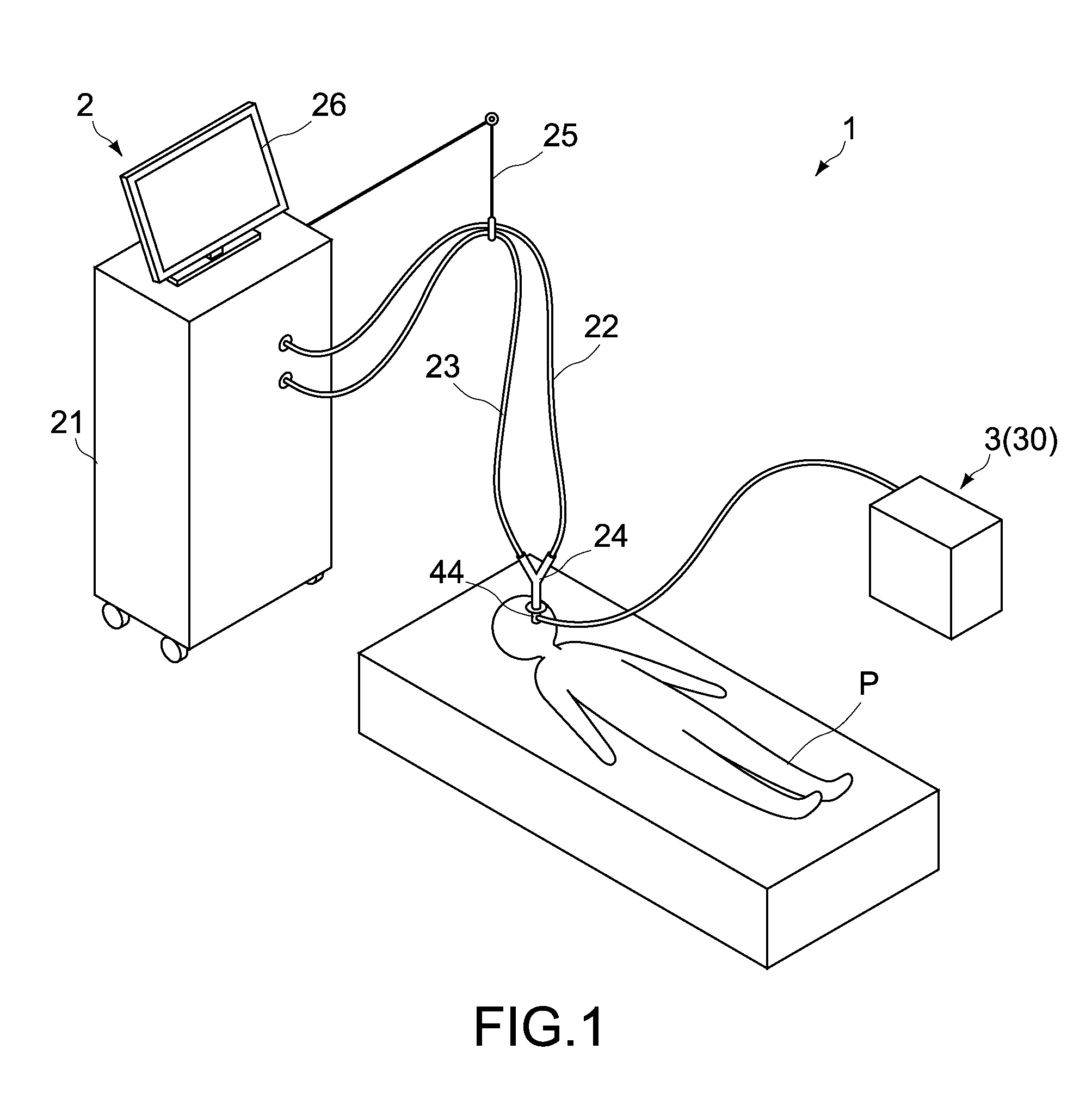
[0084]FIG. 1 is a schematic diagram showing an artificial ventilation system according to a first embodiment of the present invention. The artificial ventilation system 1 of this embodiment has an artificial ventilator 2 (artificial ventilation unit) and a sputum apparatus 3. The artificial ventilation system 1 is capable of performing an artificial respiration procedure with the artificial ventilator 2, for a patient P in a supine position. The configuration of the artificial ventilator 2 is not limited in particular, and the artificial ventilator 2 of this embodiment is applied to, for example, tracheal intubation. One example of the configuration of the artificial ventilator 2 will be described below.

[0085]The artificial ventilator 2 has a main body 21, an inspiratory circuit 22, an expiratory circuit 23, and a connecting part 24. The artificial ventilator 2 is configured to be capable of ventilating the patient P, by providing the patient P with an i...

second embodiment

[0168]FIGS. 15 and 16 are figures showing a sputum apparatus according to a second embodiment of the present invention. FIG. 15 is a schematic diagram corresponding to FIG. 2. FIG. 16 is a sectional view of main component of an intubation tube, corresponding to FIG. 8. Hereinafter, the components which are different from those of the first embodiment will be mainly described. The components similar to those of the above-described embodiment will be designated by the same reference symbols as those used in the above-described embodiment; and the description of such components will be simplified or omitted.

[0169]An artificial ventilation system including a sputum apparatus 3A according to this embodiment may be applied to a process of liberating the patient from artificial ventilation (weaning), in addition to the serious condition in which the patient is unable to breathe spontaneously. The term “weaning” herein means a process of gradually increasing the patient's spontaneous breath...


PUM


Abstract

A sputum apparatus includes a suction line, a switching unit, a measurement unit, and a control unit. The suction line has a suction inlet which aspirates sputum produced in patient's respiratory tract; and an accommodating part maintained at negative pressure, which accommodates the aspirated sputum. The switching unit is in the suction line, and can switch between first state where the suction inlet communicates with the accommodating part, and second state where the suction inlet is shutoff from the accommodating part. The measurement unit measures the expired air being aspirated into the accommodating part, under the first state. The control unit can switch the switching unit from the second state to the first state during expiration, and keep the first state when the expired air measured by the measurement unit is under predetermined value.

Description

TECHNICAL FIELD[0001]The present invention relates to a sputum apparatus, an artificial ventilation system, and a method for operating a sputum apparatus.BACKGROUND ART[0002]A patient using an artificial ventilator needs to undergo removal of sputum produced in the patient's trachea, by aspiration at periodic intervals. Such an operation for sputum is troublesome; this operation needs to be performed night and day; and nurses, caregivers, and others should bear a great burden of work.[0003]In view of this, aspirating apparatuses that automatically perform the operation for sputum have been known. For example, sputum aspirating apparatuses for aspirating sputum of patients who have been artificially ventilated by tracheostomy are described in Patent Documents 1 and 2. These sputum aspirating apparatuses are configured to continuously produce negative pressure in order to aspirate sputum; and when the negative pressure of suction path becomes high, assume that the suction tube is bloc...

Claims


Application Information

Patent Timeline
Patent Type & Authority Applications(United States)
IPC IPC(8): A61M16/04A61M16/20A61M16/00
CPCA61M16/0463A61M16/0003A61M16/0069A61M16/0434A61M2205/3334A61M2016/0027A61M2016/003A61M2202/0014A61M16/208A61M16/0051A61M16/1055A61M2016/0024A61M16/0009A61M16/0477A61M16/0833A61M16/024A61M1/74A61B5/091A61M1/00A61M16/04
Inventor HASHIMOTO, YASUHIROTAKESAWA, SHINGO
Owner ULVAC KIKO
Why Eureka
Try Eureka