Optical filter

a filter and optical filter technology, applied in the field of optical filter and display device, can solve the problems of difficult to ensure a wide viewing angle, crosstalk phenomenon may become a problem in stereoscopic image display device, etc., and achieve the effect of wide viewing angl

Active Publication Date: 2015-07-23
LG CHEM LTD
View PDF7 Cites 13 Cited by
  • Summary
  • Abstract
  • Description
  • Claims
  • Application Information

AI Technical Summary

Benefits of technology

The patent text describes a method for controlling the phase retardation characteristics of a liquid crystal layer in a liquid crystal display (LCD) or 3D device. By using a combination of multifunctional and monofunctional polymerizable compounds, the method allows for stable maintenance of the desired phase retardation characteristics. The text also mentions that the width of an optical filter region can be adjusted to improve viewing angles and brightness of the display. The technical effects of the patent text are improved control of phase retardation characteristics and stable maintenance of the desired characteristics, as well as improved viewing angles and brightness of the display.

Problems solved by technology

Crosstalk phenomenon may become a problem in stereoscopic image display devices.
While various methods may be considered to prevent the crosstalk phenomenon, it is difficult to ensure a wide viewing angle by preventing the crosstalk phenomenon without loss of brightness of a 3D image.

Method used


Image

  • Optical filter
  • Optical filter
  • Optical filter

Examples


example 1

[0127]A composition for forming a photo-alignment layer was coated on one surface of a TAC base (refractive index: 1.49, thickness: 80,000 nm) to have a dry thickness of approximately 1,000 Å, and then dried in an 80° C. oven for 2 minutes. As the composition for forming a photo-alignment layer, a composition prepared by mixing a mixture of polynorbornene (molecular weight (Mw)=150,000) having a cinnamate group of Formula 3 and an acryl monomer with a photoinitiator (Irgacure 907), and dissolving the resulting mixture in a toluene solvent to have a solid content of polynorbornene of 2 wt % was used (polynorbornene:acryl monomer:photoinitiator=2:1:0.25 (weight ratio)).

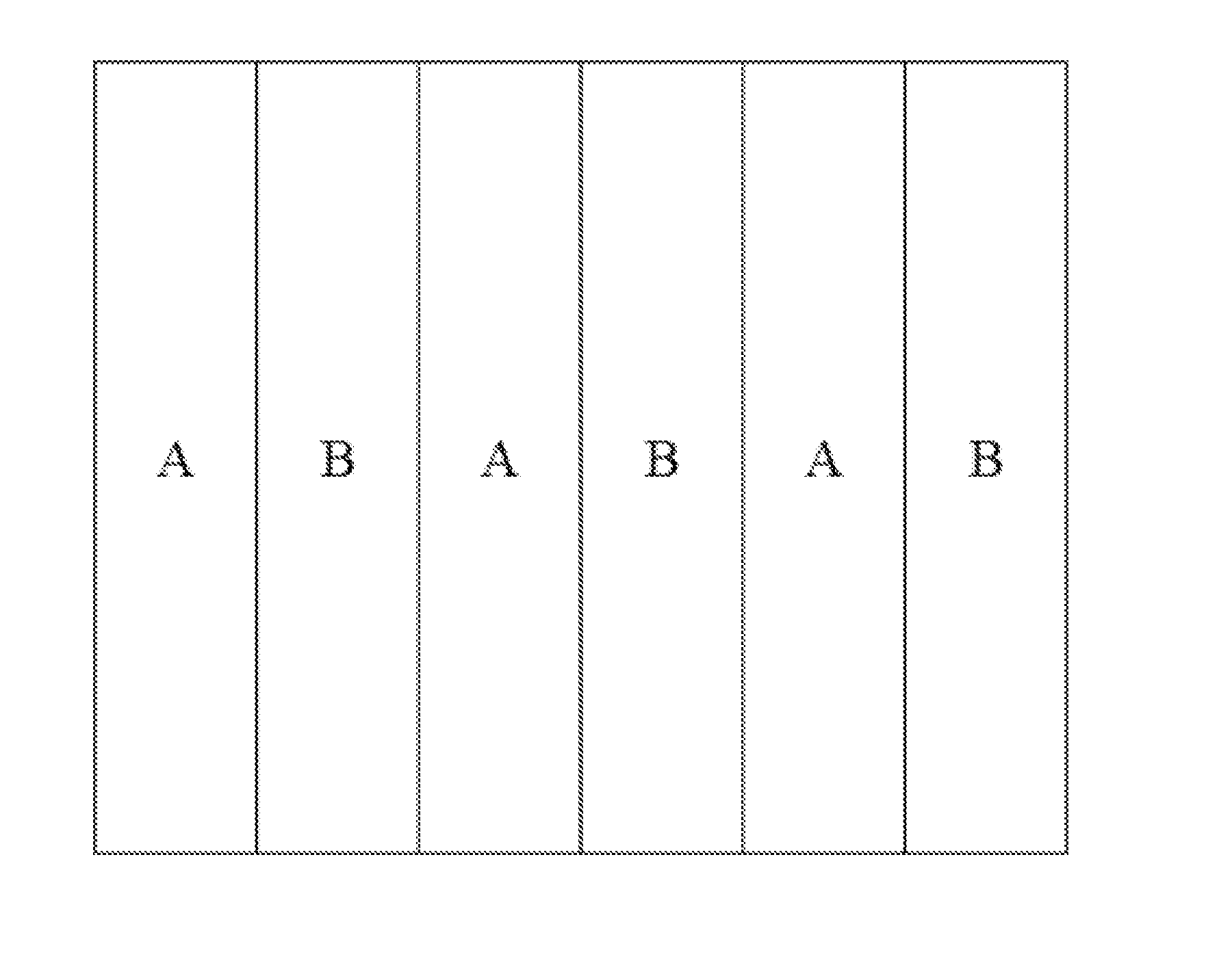
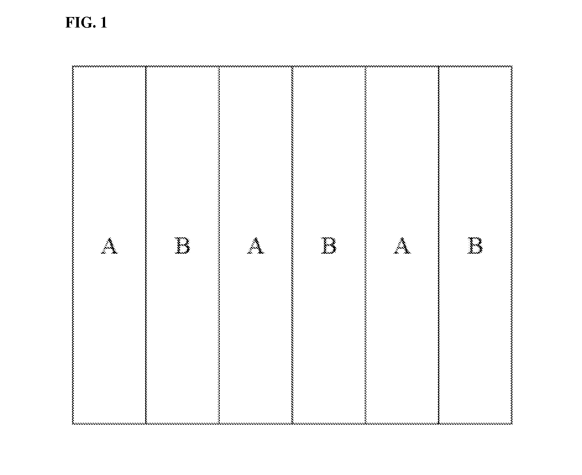
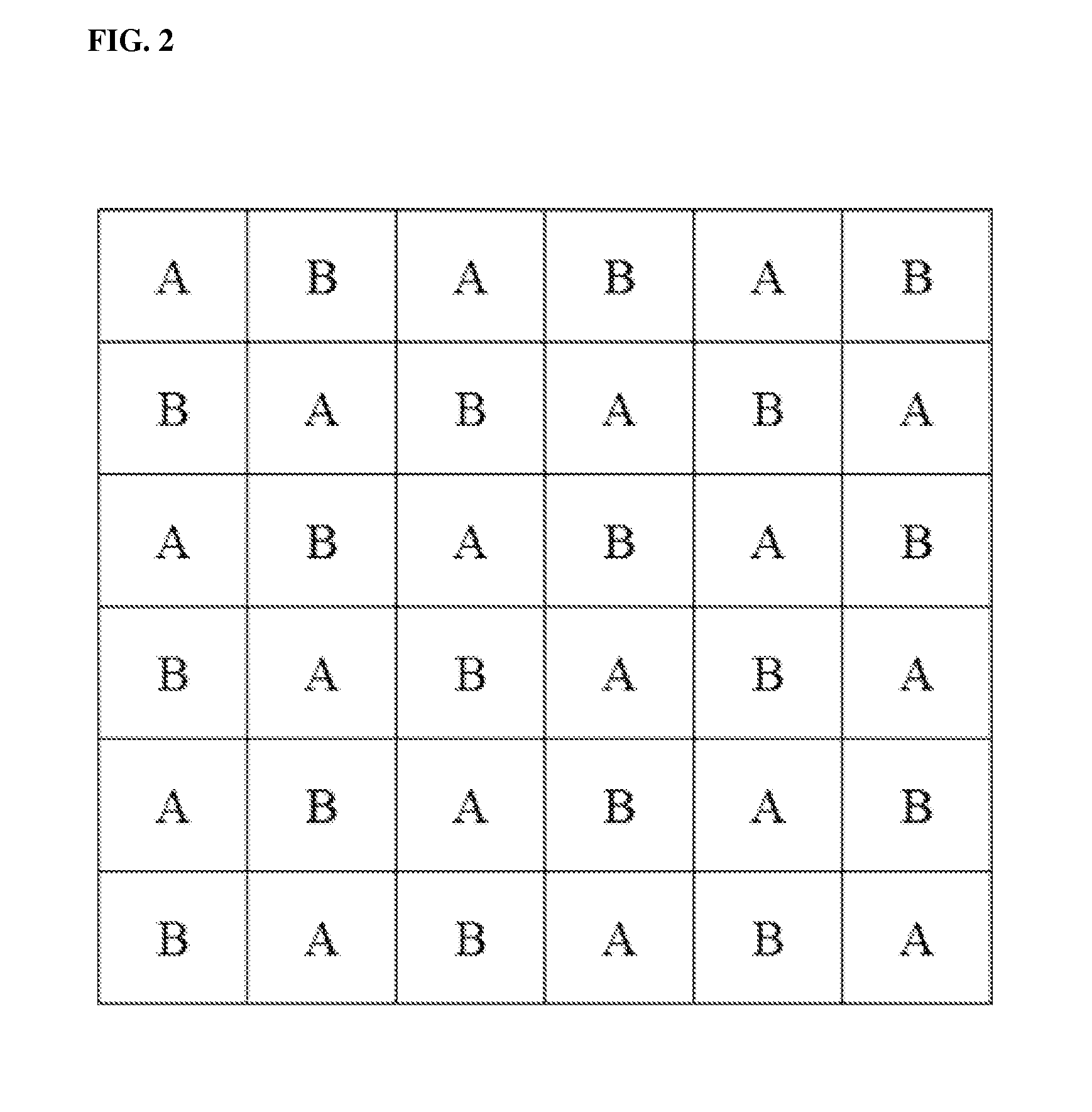
[0128]Subsequently, the dried composition for forming a photo-alignment layer was aligned according to the method disclosed in Korean Patent Application No. 2010-0009723 to form a photo-alignment layer including first and second alignment regions, which were aligned in different directions. In detail, a pattern mask hav...

example 2

[0129]An optical filter was manufactured by the same method as described in Example 1, except that printing for forming a TC region was executed on a liquid crystal layer after the liquid crystal layer was formed.

example 3

[0130]An optical filter was manufactured by the same method as described in Example 1, except that printing for forming a TC region was executed on a surface of the base layer (TAC base).


PUM

PropertyMeasurementUnit
Lengthaaaaaaaaaa
Angleaaaaaaaaaa
Fractionaaaaaaaaaa

Abstract

Provided is an optical filter and a display device. The illustrative optical filter may be applied to a stereoscopic image display device so that the stereoscopic image display device can display a 3D image at a wide viewing angle without loss of brightness.

Description

BACKGROUND[0001]1. Field[0002]The present application relates to an optical filter and a display device.[0003]2. Related Art[0004]A technique of dividing light into at least two kinds of light having different polarized states may be available in various fields.[0005]The light division technique may be applied in manufacturing a three-dimensional (3D) image. A 3D image may be realized using binocular disparity. For example, when two of two-dimensional images are respectively input to the left eye and the right eye of a human, input data is delivered to the brain and fused, and thus he / she experiences 3D perspective and reality. In such a process, the light division technique may be used.[0006]A technique of generating a 3D image may be available in 3D measurement, a 3D TV, a camera or computer graphics.[0007]Examples relating to stereoscopic image display devices to which the light division technique is applied are disclosed in Korean Patent No. 0967899 and Korean Patent Publication...

Claims


Application Information

Patent Timeline
IPC IPC(8): G02B27/22G02B5/30G02F1/1335G02F1/1334G02F1/1337G02B30/25
CPCG02B27/22G02F1/1334G02B5/3016G02F1/133512G02F1/1337G02B5/201G02B5/3083G02B30/25G02B5/20G02B30/27G02F1/133631
Inventor KIM, SHIN YOUNGJEON, BYOUNG KUNPARK, MOON SOOLEE, DA MI
Owner LG CHEM LTD
Why Eureka
Try Eureka