Pressure actuated flow control in an abrasive jet perforating tool

Active Publication Date: 2015-09-24
TD TOOLS
View PDF0 Cites 2 Cited by
  • Summary
  • Abstract
  • Description
  • Claims
  • Application Information

AI Technical Summary

Benefits of technology

[0010]Rupture pins, inserted in the jet of a perforating jet tool are configured to break when a threshold fluid pressure is applied to the jet perforating tool, according to one embodiment presented. Multiple jets are contemplated, with multiple rupture pins. Rupture pins may be configured to rupture at different pressures, thereby giving tool operator the means to selectively open jets.
[0011]According to one embodiment, rupture pins are inserted from the inside annulus of a jet perforating tool through the jet toward the external surface. The rupt

Problems solved by technology

It was soon discovered, however, that abrasive jet perforating could not only perforate, but cut (completely sever) the tubular goods into two pieces.
While abrasive jet perforating was a technical success (over 5,000 wells were treated), it was not an economic success.
The tool life in abrasive jet perforating was measured in only minutes and fluid pressures high enough to cut casing were difficult to maintain with pumps available at the time.
Consequently, very little work was performed with abrasive jet perforati

Method used


Image

  • Pressure actuated flow control in an abrasive jet perforating tool
  • Pressure actuated flow control in an abrasive jet perforating tool
  • Pressure actuated flow control in an abrasive jet perforating tool

Examples


Embodiment Construction

[0029]Abrasive jet perforating tools introduce abrasive slurry at high pressures through one or more jets located in the tool. According to one design, multiple jets can be contained within one tool. FIGS. 5A and 5B show two representations of conventional abrasive jet perforating tools with multiple jets. For example, the tool in FIG. 5B contains three jets per tool face, with two or more faces on the tool. In certain situations, it may be advantageous to open different jets at different times in a perforating job. Disclosed herein are systems and methods for using different fluid flows or pressures to operate an abrasive jet perforating tool. Opening jet locations at different pressures may aid in the operation of a perforating job.

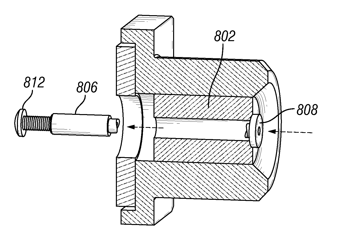
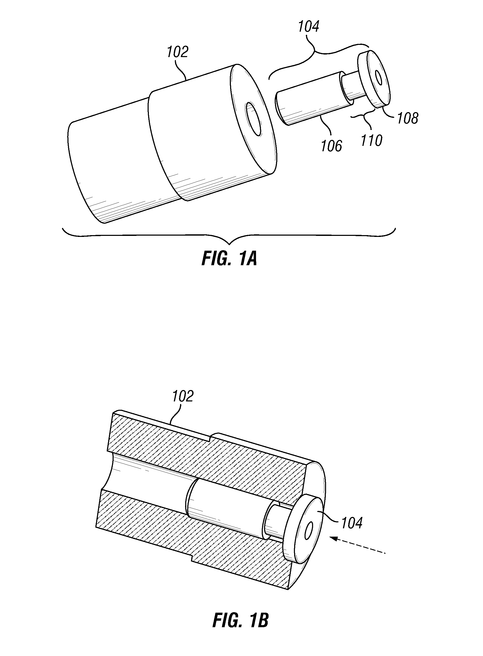
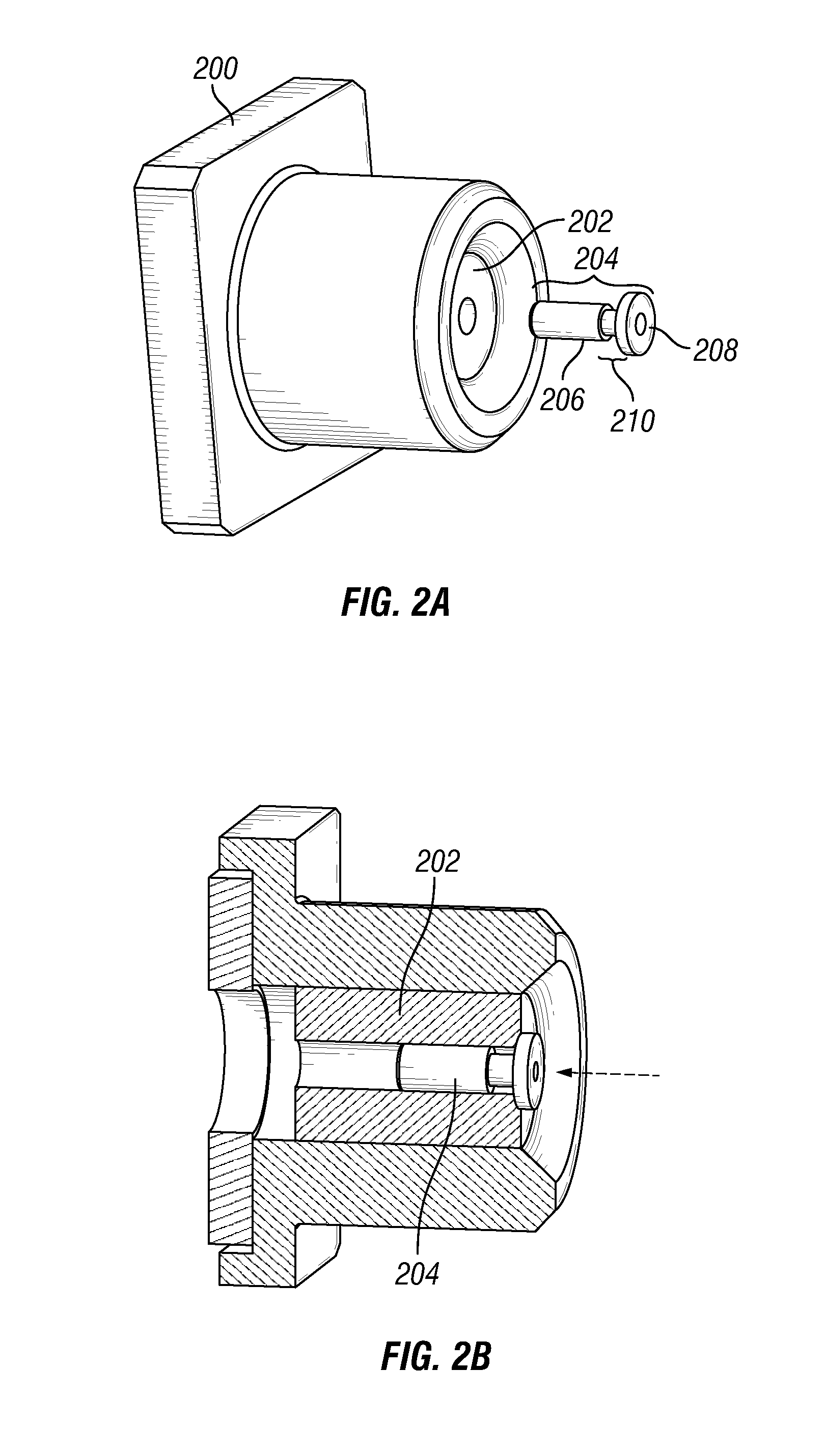
[0030]In one embodiment, a rupture pin is inserted in jets of an abrasive jet perforating tool before lowering the jet perforating tool into the well. Each rupture pin, while intact, seals a corresponding jet, or restricts the flow thereto. The rupture ...


PUM


Abstract

There is disclosed herein a method and apparatus for using rupture pins to selectively open jets on a jet perforating tool. Rupture pins inserted in jets within a jet perforating tool are configured to rupture at pre-designed thresholds, thereby opening the jet to begin a perforating job, or to circulate fluid through the tool. Also disclosed are systems and methods for holding the rupture pins within the tool prior to rupture.

Description

CROSS REFERENCE[0001]The present application claims priority to U.S. provisional application Ser. No. 61 / 968,435, which was filed on Mar. 21, 2014, entitled Pressure Actuated Flow Control in an Abrasive Jet Perforating Tool, the disclosure of which is incorporated by reference herein in its entirety.FIELD OF INVENTION[0002]This invention relates generally to the field of treating wells to stimulate fluid production. More particularly, the invention relates to the field of high pressure abrasive fluid injection in oil and gas wells.BACKGROUND OF THE INVENTION[0003]Abrasive jet perforating uses fluid slurry pumped under high pressure to perforate tubular goods around a wellbore, where the tubular goods include tubing, casing, and cement. Since sand is the most common abrasive used, this technique is also known as sand jet perforating (SJP). Abrasive jet perforating was originally used to extend a cavity into the surrounding reservoir to stimulate fluid production. It was soon discover...

Claims


Application Information

Patent Timeline
IPC IPC(8): E21B43/114E21B41/00
CPCE21B41/0078E21B43/114
Inventor DOTSON, THOMAS L.
Owner TD TOOLS
Why Eureka
Try Eureka