Portable lighting device

a lighting device and portable technology, applied in the field of portable lighting devices, can solve the problems of limited illumination effect of conventional flashlights, inability to provide illumination to a relatively large area, and difficult for users to keep an uncomfortable holding posture for a relatively long time, and achieve good illumination effect and cost-effective

Inactive Publication Date: 2015-09-24
YUYAO JINFENG ELECTRIC APPLIANCE
View PDF7 Cites 53 Cited by
  • Summary
  • Abstract
  • Description
  • Claims
  • Application Information

AI Technical Summary

Benefits of technology

[0010]Another advantage of the invention is to provide a portable lighting device, wherein the direction adjusting arrangement is capable of rotating with respect to the light housing, so that an angle between the direction adjusting arrangement and the light housing can be adjusted, and thus the light beams of light source can be directed to a desired orientation.
[0011]Another advantage of the invention is to provide a portable lighting device, wherein the direction adjusting arrangement may define a rotation cavity so that an end portion of the light housing is capable of rotating in and out of the rotation cavity, so that the projecting direction of the light beams of the light source can be selectively adjusted.
[0012]Another advantage of the invention is to provide a portable lighting device, wherein an end portion of the light housing may define the rotation cavity, so that the direction adjusting arrangement may rotate in and out of the rotation cavity, so that the projecting direction of the light beams of the light source can be selectively adjusted.
[0013]Another advantage of the invention is to provide a portable lighting device, wherein the direction adjusting arrangement may be used for affixing to the environment, enabling the portable lighting device being mounted to the environment for providing illumination, so that there is no need for holding the portable lighting device by the hands of the user, and thus the hands of the user can be set free for doing other jobs.
[0014]Another advantage of the invention is to provide a portable lighting device, which is capable of being worn on the user so as to be constructed to be a wearable lighting device, so that the lighting device is more convenient for taking out to outdoor cavities.
[0015]Another advantage of the invention is to provide a portable lighting device, wherein the light source may comprise one or more light units each provides an illumination pattern, each of the light units may comprise one or more LED illumination members, so that the LED light source is cost-effective and also provides a good illumination effect.

Problems solved by technology

However, this type of flashlight has several drawbacks.
First of all, the light beams of the LED light source of the conventional flashlight only project out through the head portion of the handheld housing, so that the illumination effect of the conventional flashlight is limited by its spot light pattern.
In other words, the conventional flashlight cannot be used to provide illumination to a relatively large area.
Therefore, the user has to user his or her hand to adjust the angle and position of the handheld housing so as to provide a desired light projecting direction, and sometime it is really difficult for the user to keep an uncomfortable holding posture for a relatively long time.
In other words, the conventional flashlight cannot be affixed to the environment when it is used for illumination, so that the hand of the user holding on the handheld housing cannot be spared for other uses.
However, as discussed above, the conventional flashlight is still inconvenient to use, so that it cannot fulfill the need of the user.

Method used


Image

  • Portable lighting device
  • Portable lighting device
  • Portable lighting device

Examples


Embodiment Construction

[0052]The following description is disclosed to enable any person skilled in the art to make and use the present invention. Preferred embodiments are provided in the following description only as examples and modifications will be apparent to those skilled in the art. The general principles defined in the following description would be applied to other embodiments, alternatives, modifications, equivalents, and applications without departing from the spirit and scope of the present invention.

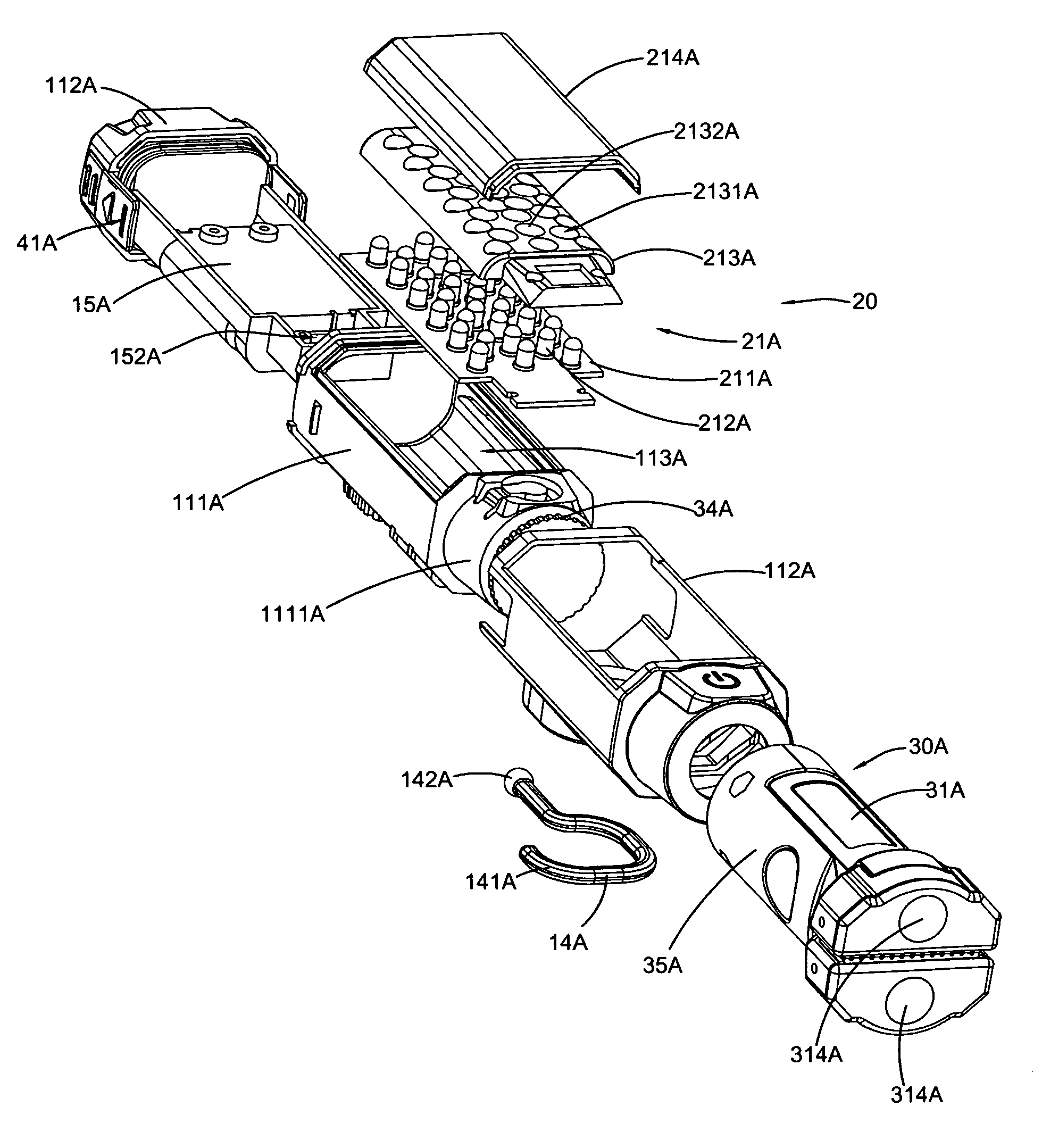
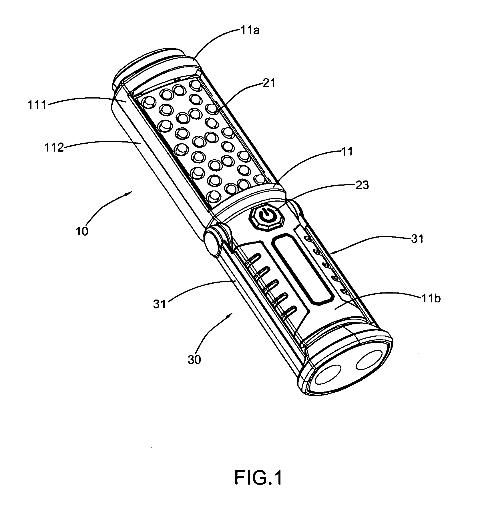
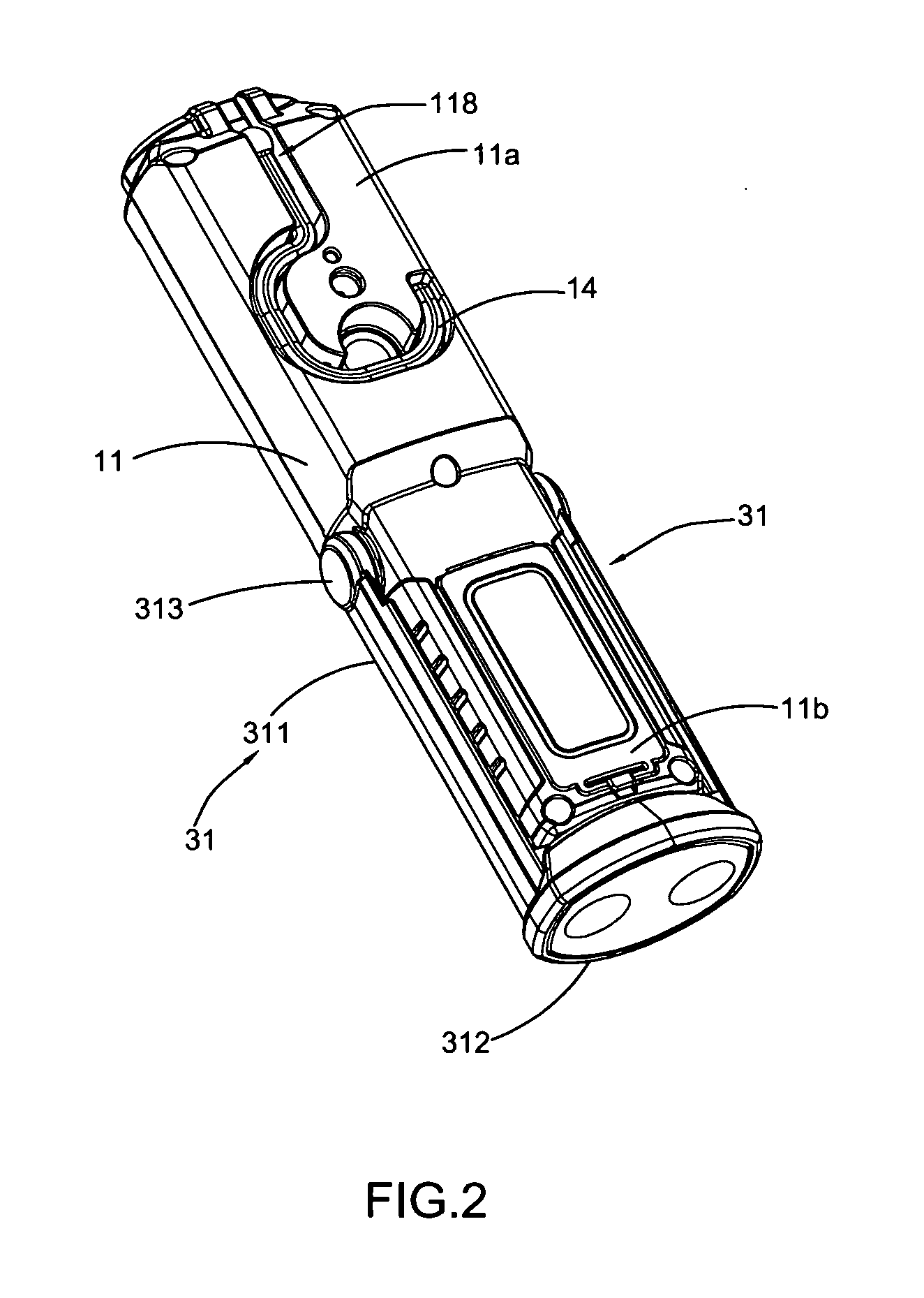
[0053]Referring to FIGS. 1 to 11 of the drawings, a portable lighting device according to a first preferred embodiment of the present invention is illustrated. As shown in the drawings, the portable lighting device comprises a light housing 10, a light source 20, and a direction adjusting arrangement 30. The light source 20 is supported by the light housing 10 and the light beams of the light source 20 project out from the light housing 10 for providing illumination. The direction adjusting arran...


PUM


Abstract

A portable lighting device includes a light housing having a housing body defining a receiving cavity, a light source supported in the receiving cavity of the housing body, and a direction adjusting arrangement which is rotatably mounted with the housing body in such a manner that a projecting direction of the light source is capable of being adjusted by means of a relative movement between the housing body and the direction adjusting arrangement.

Description

NOTICE OF COPYRIGHT[0001]A portion of the disclosure of this patent document contains material which is subject to copyright protection. The copyright owner has no objection to any reproduction by anyone of the patent disclosure, as it appears in the United States Patent and Trademark Office patent files or records, but otherwise reserves all copyright rights whatsoever.BACKGROUND OF THE PRESENT INVENTION[0002]1. Field of Invention[0003]The present invention relates to a lighting device, and more particularly to a portable lighting device which is capable of adjusting a light projecting direction by means of the relative movement between a movable direction adjusting arrangement and a light housing thereof.[0004]2. Description of Related Arts[0005]A current lighting device, especially an outdoor lighting fixture such as a flashlight, generally adopts an LED array as a light source, so that it can provide a good lighting effect and a relatively long period of usage before it should b...

Claims


Application Information

Patent Timeline
Patent Type & Authority Applications(United States)
IPC IPC(8): F21V19/00F21V21/096F21V14/00F21L4/00F21L4/02F21V21/088F21V21/08F21V7/22
CPCF21V19/00F21V21/0832F21V21/0965F21V7/22F21L4/005F21W2131/10F21V21/0885F21V14/00F21Y2101/02F21W2111/10F21L4/027F21L4/04F21V21/30F21W2131/1005F21Y2115/10
Inventor ZHANG, JIFENG
Owner YUYAO JINFENG ELECTRIC APPLIANCE
Why Eureka
Try Eureka