Multi-part, manifold and method of making the manifold

Inactive Publication Date: 2015-12-03
SPX FLOW INC
View PDF5 Cites 1 Cited by
  • Summary
  • Abstract
  • Description
  • Claims
  • Application Information

AI Technical Summary

Benefits of technology

[0005]The foregoing needs are met, to a great extent, by the present invention, wherein in one aspect an appar

Problems solved by technology

However, there may be instances where a rectang

Method used


Image

  • Multi-part, manifold and method of making the manifold
  • Multi-part, manifold and method of making the manifold
  • Multi-part, manifold and method of making the manifold

Examples


Example

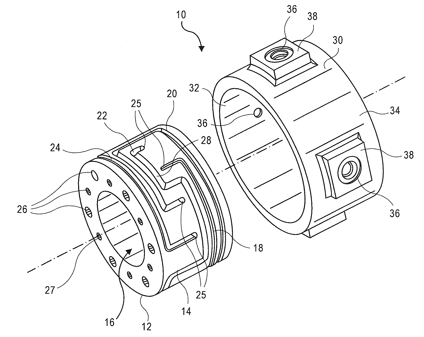
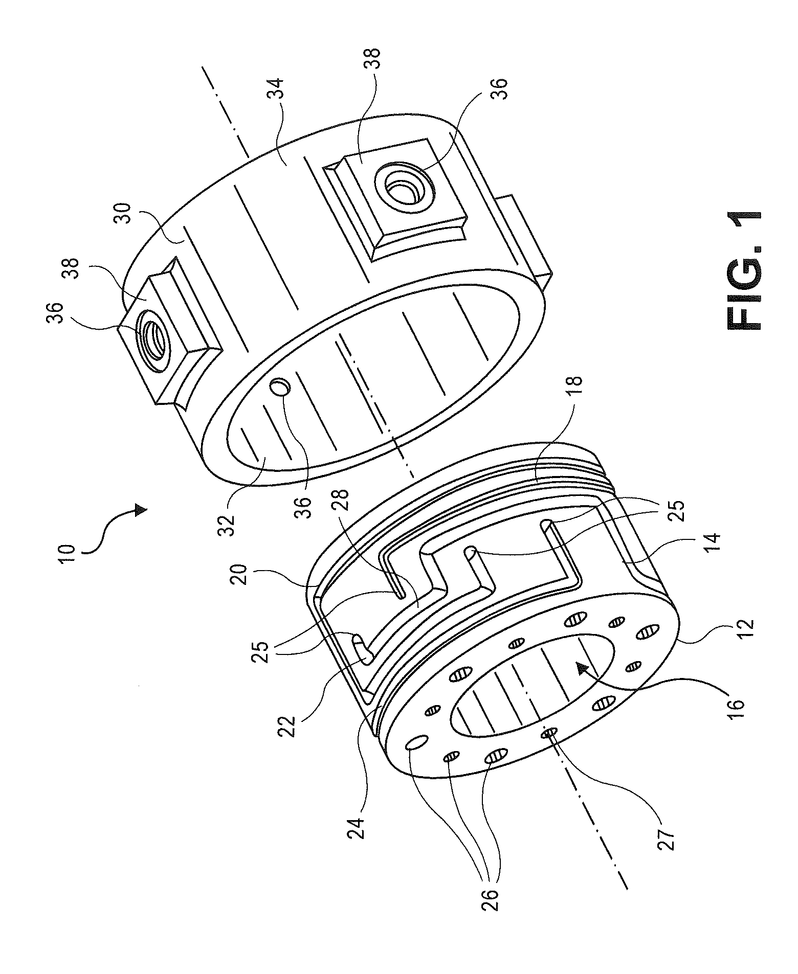
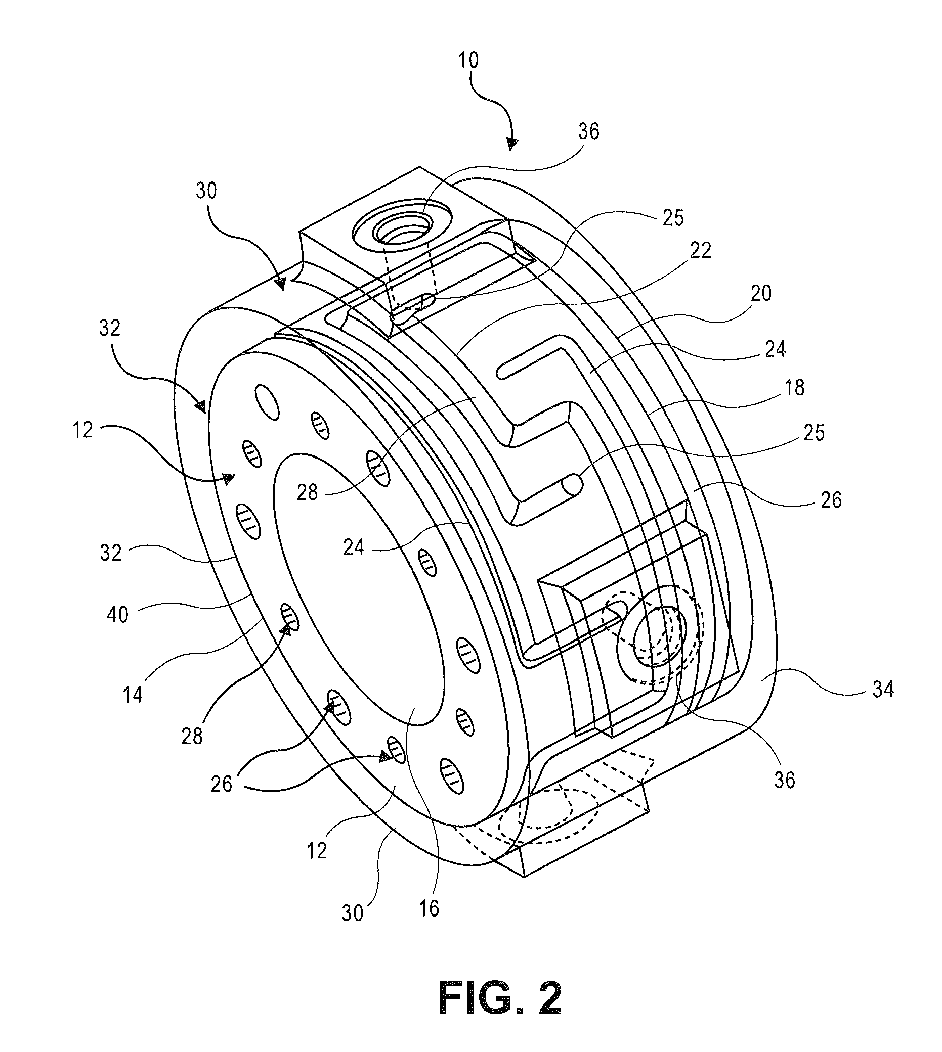
[0022]According to some embodiments, a generally circular shaped manifold 10 is provided. The manifold 10 may include an inner body 12. The inner body 12 may have an outer surface 14 of the inner body 12. Optionally, the inner body 12 may have a void or hole 16 in its center portion. In other embodiments, the inner body 12 may be solid at the center portion.

[0023]Grooves or pathways 18, 20, 22, and 24 may be formed on the outer surface 14 of the inner body 12. The grooves 18, 20, 22, and 24 are pathways which allow a fluid to flow within the manifold 10. For example, in some embodiments, various axial pathways 26 may be fluidly connected to each other via the grooves or pathways 18, 20, 22, and 24.

[0024]When the inner body 12 is tightly fit within the outer body 30, as shown in FIG. 2, the grooves or pathways 18, 20, 22, and 24 are fluidly isolated from each other. The fluid flows through the pathways 18, 20, 22, and 24 to provide fluid communication within the manifold 10 to variou...


PUM


Abstract

A manifold is provided. The manifold includes: a first body having an outer surface; a second body having an inner surface corresponding to the outer surface of the first body and the first body is micro-welded to the second body; and a groove formed in one or both of the outer and inner surfaces, wherein the first body is dimensioned to fit within the second body so that the outer surface contacts the inner surface and the groove forms a fluid passage located between the first and second bodies, the fluid passage having an inlet and an outlet. Also in some embodiments a method of forming a manifold is provided. The method includes: filling a die with powdered metal having grains; compressing the powdered metal in the die thereby forming a first body; removing the compressed part from the die; contacting the first body to a second body subjecting the bodies to heat; and forming micro-weld between grains of metal between the two bodies.

Description

CROSS-REFERENCE TO RELATED APPLICATIONS[0001]This application claims priority to, and is a continuation-in-part application of, pending U.S. patent application entitled, “A Muli-Part, Tapered, Concentric Manifold and Method of Making the Manifold” filed May 19, 2015, having Ser. No. 14 / 716,755 which is a continuation-in-part application of, pending U.S. patent application entitled, A Multi-Part Concentric Manifold and Method of Making the Manifold, filed Jul.,9, 2013, having Ser. No. 13 / 937,509. Priority to of all of the above mentioned applications is claimed herein and the disclosure of these applications are incorporated herein by reference in their entirety.FIELD OF THE INVENTION[0002]The present invention relates generally to a manifold. More particularly, the present invention relates to a multipart, concentric, tapered, compact manifold.BACKGROUND OF THE INVENTION[0003]Manifolds are traditionally used to assist in the routing of various fluids. Often a single housing or block...

Claims


Application Information

Patent Timeline
IPC IPC(8): F16L41/02
CPCY10T137/0402F16L41/02Y10T137/85938F16L13/004F16L13/0209F16L41/03
Inventor LANDRUM, MICHAEL T.BOOTH, DWIGHT
Owner SPX FLOW INC
Why Eureka
Try Eureka