Tank retainer in an aircraft

a technology for aircraft and tanks, applied in the direction of cosmonautic components, gas/liquid distribution and storage, cosmonautic parts, etc., can solve the problems of not-significant impact on the mass of the craft, the need for long operation times for assembling and dismantling the interface, and the inability to apply launcher solutions unmodified to an aircraft of spaceplane type, etc., to compensate for the stress. the effect of the stress

Inactive Publication Date: 2015-12-17
ARIANEGRP SAS
View PDF19 Cites 10 Cited by
  • Summary
  • Abstract
  • Description
  • Claims
  • Application Information

AI Technical Summary

Benefits of technology

[0024]Still with the concern of guaranteeing the desired performance, the device needs in particular to minimize the evaporation of cryogenic propellants through thermal losses between the tanks and the bearing structure.
[0028]relatively quick and easy fitting and removal of the tanks confined to a very tight space, and quick inspection operations;
[0031]minimization of the overall mass impact, at the attachment points as such, but also of the reinforcers needed at the level of the airplane structure and of the structural parts of the tanks; and

Problems solved by technology

These solutions entailing numerous connecting elements allow good distribution of load at the interfaces, but have the major disadvantages of a not-insignificant impact on the mass of the craft and the need for lengthy operation times for assembling and dismantling the interfaces.
As a result, launcher solutions cannot be applied unmodified to an aircraft of the spaceplane type.
These interface devices are not, however, particularly well suited to compensating for the stresses induced by differential thermal expansions which are non-zero.
Finally, these devices are applicable very little if at all to installations in which the volume available for the supporting device is very small.
Finally, some of the support devices proposed for equalizing the stresses may prove highly penalizing in terms of mass when applied to rocket propulsion tanks.
This is because this solution, like most of the solutions usually adopted for the maritime support of cryogenic tanks, essentially for liquid natural gas, is unable to optimize the entire tank+bearing structure+support elements mass package to the level required for the space or aeronautical domain.
Likewise, thermal losses, which are negligible in comparison with the volumes transported in maritime transport, are no longer negligible on the scale of aeronautical craft and spacecraft.
These supports, suited to tanks with toroidal bottoms, constitute just part of the support device which is more complex and requires either the addition in the airplane of a support structure of conical type, which is bulky and penalizing in terms of mass, or that the forces at the front of the tank be reacted on a pressurized end wall that is designed and engineered to perform this function and is therefore once again heavy and bulky.
In the same spirit, any unused volume is to be proscribed, and the diameters of the cryogenic tanks are defined to be as close as possible to the diameters of the fuselage, thus placing great constraints on how interface components are arranged.

Method used


Image

  • Tank retainer in an aircraft
  • Tank retainer in an aircraft
  • Tank retainer in an aircraft

Examples


Embodiment Construction

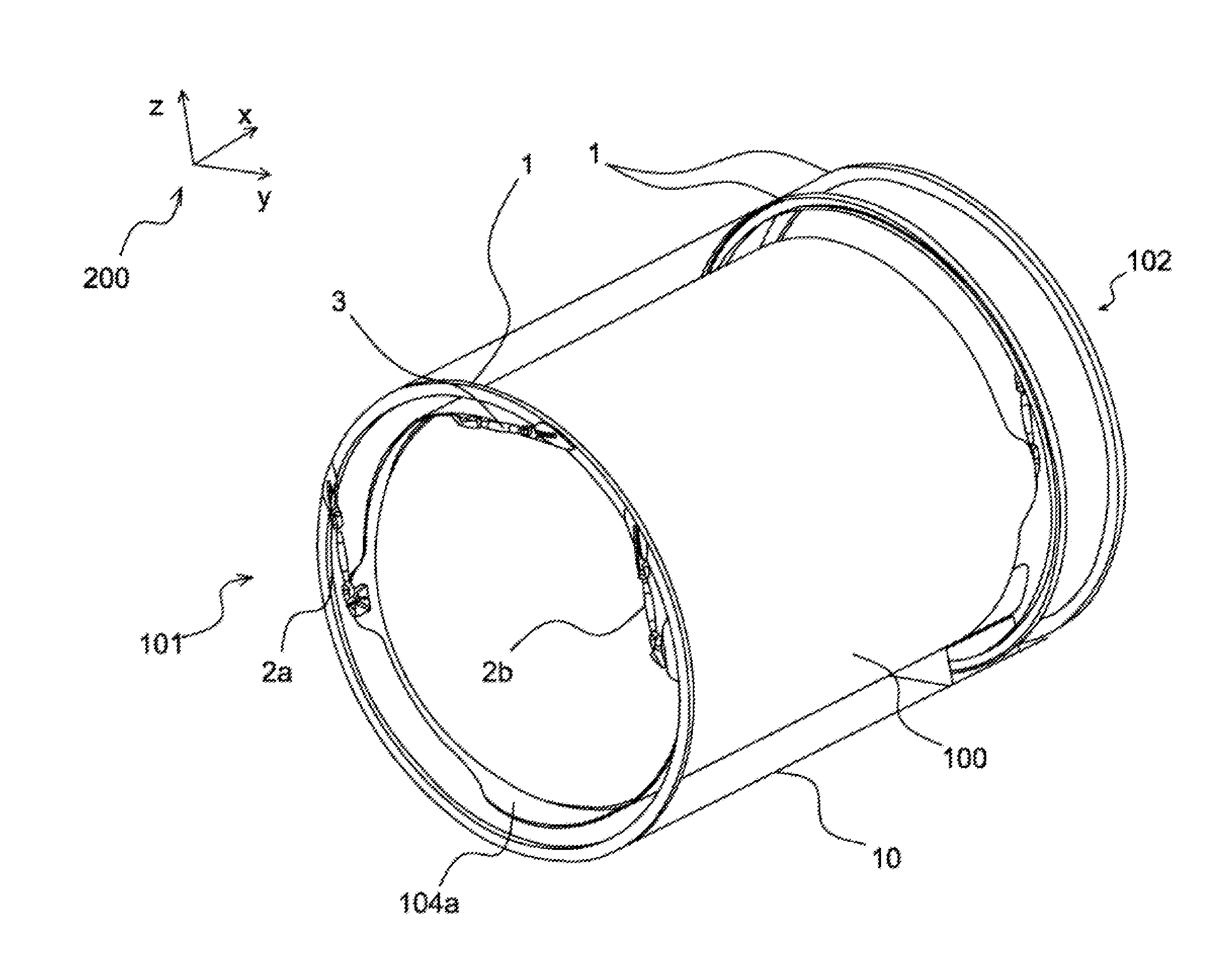
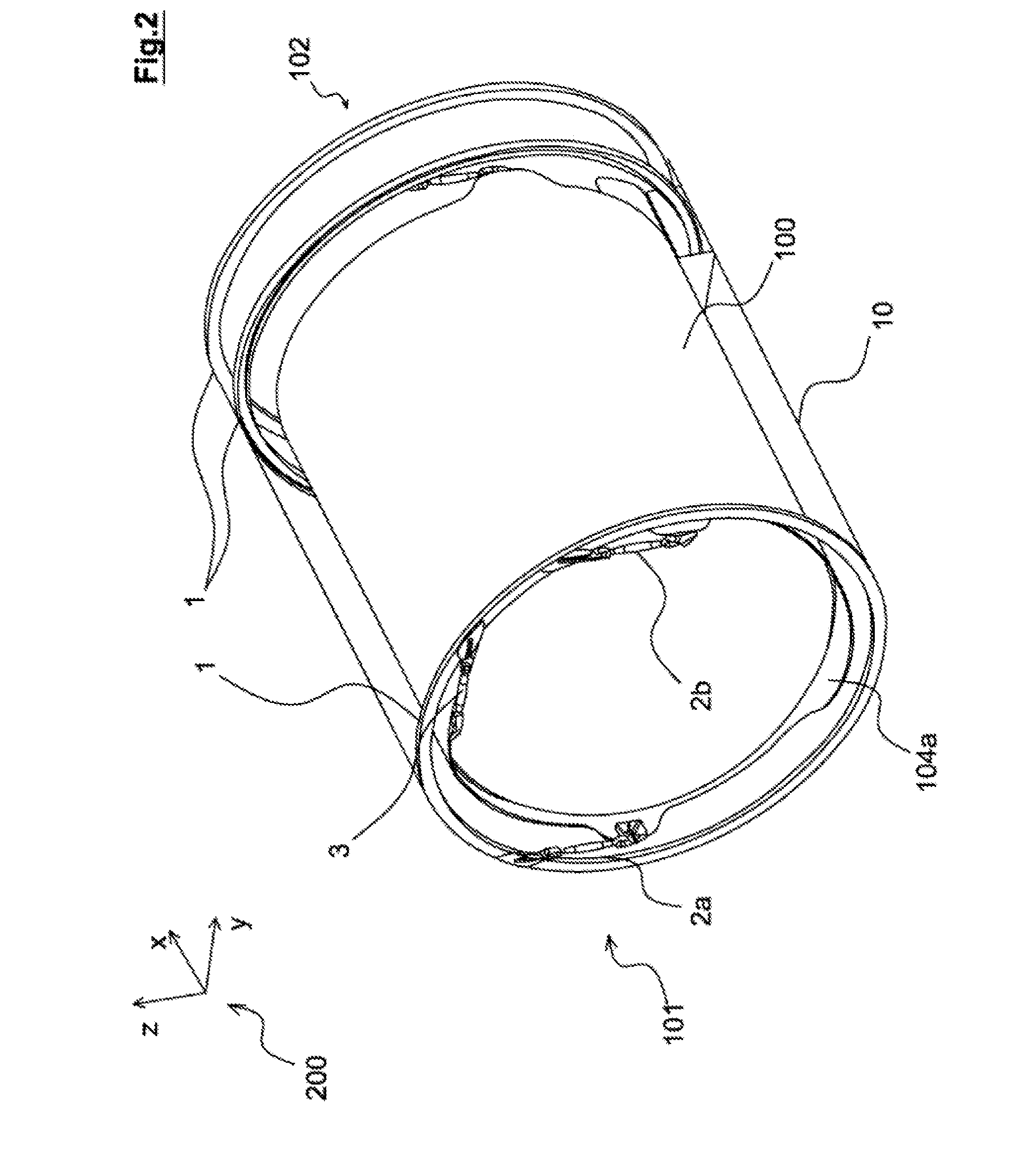
[0056]The disclosed embodiment relates to a device for supporting and holding a tank 100 as depicted in FIGS. 2 and 3, of cylindrical or conical overall shape and of main axis X, a horizontal axis corresponding to the main axis of the aircraft according to the disclosed embodiment.

[0057]The device in general comprises a number of tank retaining means, these means being divided into three groups: first means intended to support the tank, one or more second means intended to restrain one end of the tank in a lateral direction perpendicular to the main axis X, and a third retaining means creating an anchor point anchoring the tank with respect to the fuselage of the aircraft.

[0058]The device thus comprises, in the first place, a pair of first means 2a, 2b, 2c, 2d of retaining the tank along an axis Z at each of a first 101 and of a second 102 end of the tank. In the example, the axis Z is a vertical axis, the first means supporting the tank in the fuselage of the aircraft.

[0059]The fir...


PUM


Abstract

The invention concerns a tank retainer for retaining a tank in the fuselage of an aircraft which includes, between the tank and a frame rigidly connected to the fuselage of the aircraft, a hinged retaining means and a fastening rod on which said hinged retaining means is mounted. Advantageously, the hinged retaining means is intended to be connected to a rear end of the tank and the fastening rod is suitable for being mounted on the frame rigidly connected to the fuselage of the aircraft and, preferably, the hinged retaining means comprises a ball joint.

Description

CROSS REFERENCE TO RELATED APPLICATIONS[0001]This application is the National Stage of International Application No. PCT / EP2014 / 052144, having an International Filing Date of 4 Feb. 2014, which designated the United States of America, and which International Application was published under PCT Article 21(s) as WO Publication No. 2014 / 122127 A1, and which claims priority from, and the benefit of French Application No. 1350987, filed 5 Feb. 2013, the disclosures of which are incorporated herein by reference in their entireties.BACKGROUND[0002]1. Field[0003]The presently disclosed embodiment relates to a device for retaining a tank in an aircraft and more particularly one suited to holding cryogenic propellant tanks in a fuselage of an aircraft such as an airplane and notably a spaceplane. Such a device, which in the relevant art is referred to as a “supporting device”, is notably suited to supporting tanks of cylindrical or conical shape supplying a rocket motor of a spaceplane with p...

Claims


Application Information

Patent Timeline
Patent Type & Authority Applications(United States)
IPC IPC(8): B64D37/04B64G1/40B64D37/30B64D37/06
CPCB64D37/04B64D37/30B64G1/402B64D37/06F17C2205/0192F17C2221/08F17C2270/0197F16C11/0695
Inventor CHEVROLLIER, SAMUELABADIE-LAHAILLE, ROBERTMEZIERES, PASCALFAURE, BENJAMINBERTRAND, JEROMECORABOEUF, YOHANNSANTERRE, ANGELIQUE
Owner ARIANEGRP SAS
Why Eureka
Try Eureka