Volumetric hydraulic machine for pressurized water supply

a hydraulic machine and volumetric technology, applied in machines/engines, reciprocating piston engines, positive displacement engines, etc., can solve the disadvantages of said turbines only applying to aqueduct supplies with high pressure and flow rate, disadvantageous wear of paddles of said turbines, and the effect of said volumetric turbines is less

Inactive Publication Date: 2015-12-24
BRIGAGLIA ALBERTO +1
View PDF15 Cites 0 Cited by
  • Summary
  • Abstract
  • Description
  • Claims
  • Application Information

AI Technical Summary

Benefits of technology

[0009]The object of the present invention is to make a high-efficiency volumetric hydraulic machine which exploits the excess kinetic energy of the aqueduct supplies in a wide range of pressure and flow rate values without interrupting water supply.

Problems solved by technology

Said turbine is disadvantageously only applied to aqueduct supplies with a high pressure and flow rate.
Furthermore, said paddles of said turbine are disadvantageously subject to wear caused by the minerals in the water.
Said volumetric turbine becomes less effective over time thus disadvantageously being fragile, given that said paddles are pushed by respective compression springs against an inner wall of a fluid containment cylinder to increase the pressure.
Said turbine is not capable of effectively regulating the excess water flow, given that a sudden strong increase of the water inlet risks breaking the turbine mechanism.
It is disadvantageous because said hydraulic machine interrupts the water flow of the aqueduct water network and the pistons are in risk of breaking.

Method used


Image

  • Volumetric hydraulic machine for pressurized water supply
  • Volumetric hydraulic machine for pressurized water supply
  • Volumetric hydraulic machine for pressurized water supply

Examples


Embodiment Construction

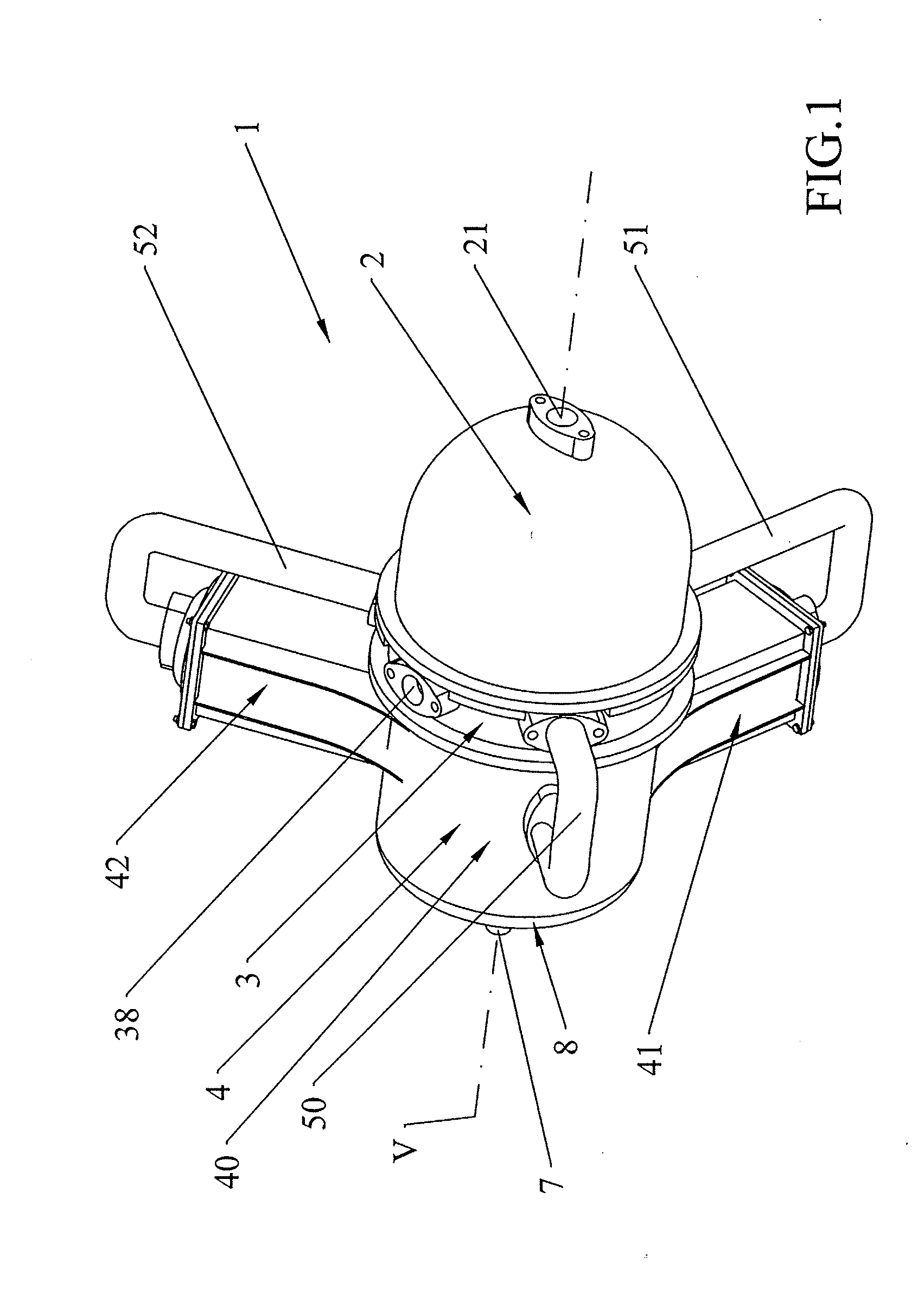
[0049]With reference to the above-listed figures, a hydraulic machine 1 for water supply in pressure can be noted comprising a cover 2 of dome-shape which closes on a cylindrical distribution box 3.

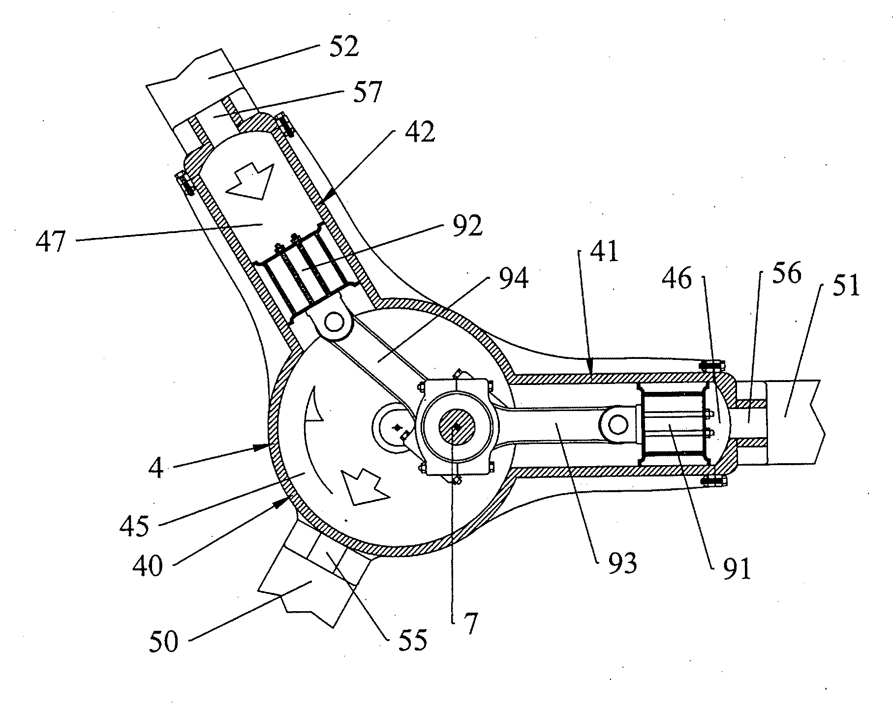
[0050]Said distribution box 3 is mounted in turn on a monoblock 4 comprising a central cylindrical body 40 and two arms: a first arm 41 and a second arm 42 arranged at 120° between them.

[0051]As shown in FIG. 3, a rotating slide valve 6, which is inside cover 2, is rotatably mounted on said distribution box 3.

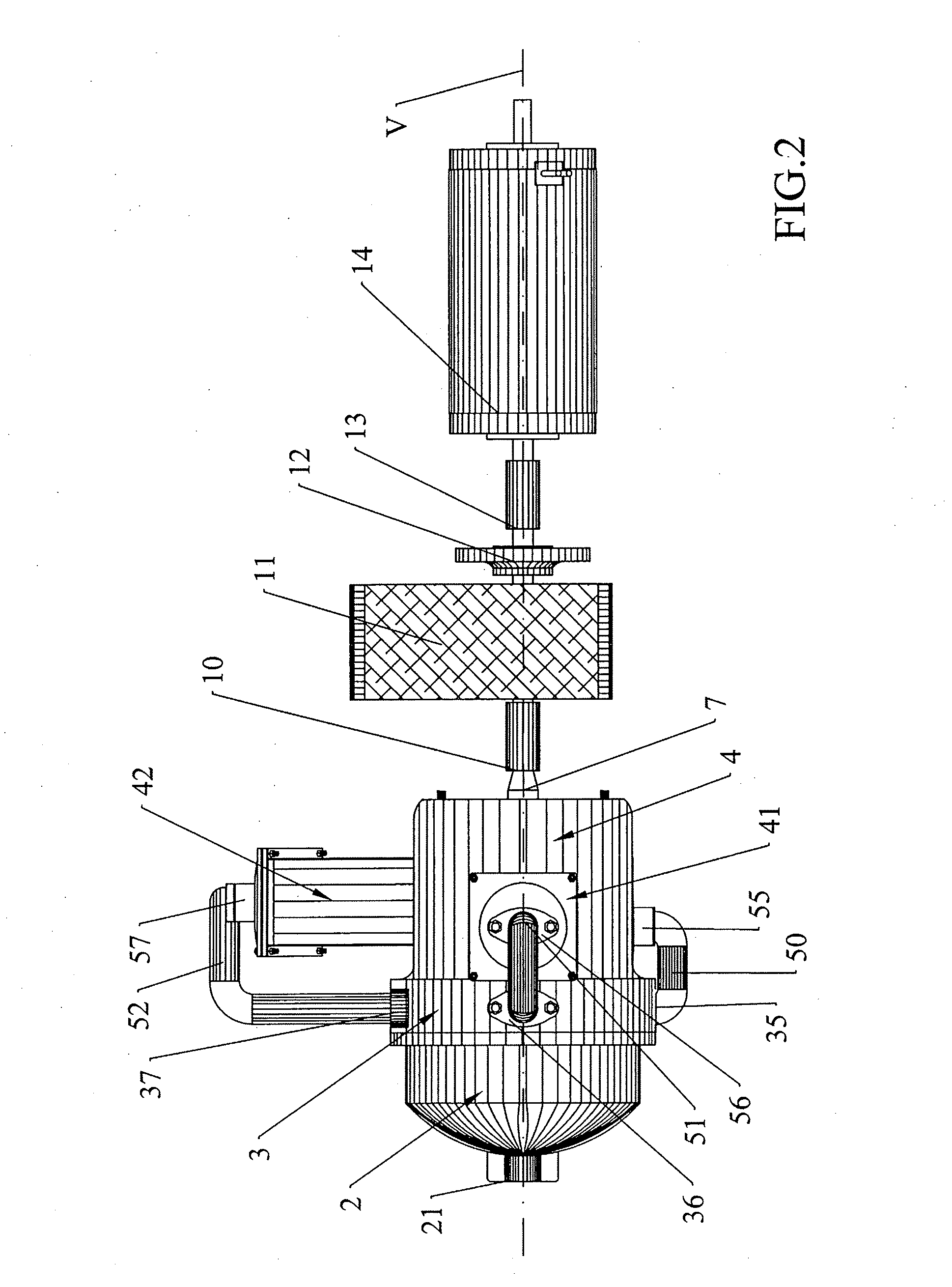
[0052]An inlet flange 21 for the water deriving from an aqueduct water supply (not shown in the figures) opens on the top of the dome of said cover 2. Said inlet flange 21 is crossed by an axis V which passes the whole hydraulic machine 1 from the front part to the rear part, as shown in particular in FIGS. 2 and 3.

[0053]As shown in FIG. 3, said cover 2 encloses a front chamber 20 on the distribution box 3, said front chamber 20 serving advantageously as basin collector for the water...


PUM


Abstract

A volumetric hydraulic machine for water supply in pressure comprising a rotating slide valve integral with a crankshaft which rotates around an axis, said rotating slide valve is rotatably mounted on a distribution box that comprises a plurality of cavities respectively connected to a plurality of pipes of which an outlet pipe connected with the output in the water supply, the other remaining pipes of said plurality of pipes each respectively connected with only one of a plurality of chambers of a monoblock which integrally mounts said distribution box, said monoblock comprising a central chamber and at least a pair of further chambers, said crankshaft engaging at least a pair of connecting rods mounting pistons.

Description

[0001]The present invention relates to a volumetric hydraulic machine for water supply in pressure.BACKGROUND OF THE INVENTION[0002]Hydroelectric generators on the market exploit the pressure force of the water pipes to cause the turbines to rotate and generate electric energy. In order for the hydroelectric turbine generator to efficiently generate electric current, there is a need on the one hand to increase the speed of the water flow on the turbine blades or propellers, and on the other, to make the geometry of the turbine blades or propellers as effective as possible.[0003]The pipes of the aqueduct supplies have water flow pressures which change significantly over time due to weather factors and use by the population or by industries.[0004]Patent IT2011TV0045A1 describes a volumetric paddle turbine capable of exploiting the excess pressure of the aqueduct supplies to generate electric energy.[0005]Said turbine is disadvantageously only applied to aqueduct supplies with a high p...

Claims


Application Information

Patent Timeline
Patent Type & Authority Applications(United States)
IPC IPC(8): F03C1/24F03C1/26F01B1/06F03C1/04
CPCF03C1/2454F01B1/06F03C1/26F03C1/04F01B1/062F03C1/0444F03C1/14F03B5/00Y02E10/20
Inventor PINNA, FRANCO
Owner BRIGAGLIA ALBERTO
Why Eureka
Try Eureka