Fluid kinetic energy power generation device

A power generation device, fluid technology, used in hydroelectric power generation, engine components, machines/engines, etc.

Pending Publication Date: 2021-08-20
范文鸿
View PDF6 Cites 0 Cited by
  • Summary
  • Abstract
  • Description
  • Claims
  • Application Information

AI Technical Summary

Problems solved by technology

How to collect the kinetic energy of these irregular movements, control it, make it obedient, and use it for me, there is no ideal technology yet

Method used


Image

  • Fluid kinetic energy power generation device
  • Fluid kinetic energy power generation device
  • Fluid kinetic energy power generation device

Examples


Embodiment 1

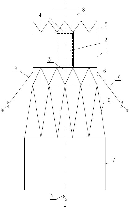
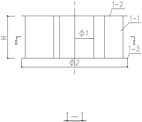
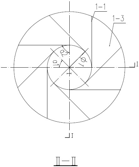
[0065] In a fluid kinetic energy power generation device, the fluid guide shell 1 is selected as type A; the impeller 2 is selected as type A, the outer diameter of the impeller 2 is 500 mm, the height H is 410 mm, and it is installed horizontally. The fluid diversion casing 1 is made of a steel plate with a thickness of 3 mm. The upper shell plate 1-2 and the lower shell plate 1-3 are ring plates, the inner diameter Φ1 is 540 mm, and the outer diameter Φ2 is 1500 mm. The partition 1-1 is rectangular, the length X is 700 mm, and the width y is 404 mm. Choose a1 equal to 45 degrees. Place the lower shell plate 1-3 on a horizontal plane, divide its inner circle Φ1 into 8 equal parts, and obtain 8 central angles a1 equal to 45 degrees. A total of 8 intersection points of one side of each central angle a1 and the circle of Φ1 are used as starting points for setting the partition 1-1. Preferably, a2 is equal to 90 degrees, that is, the partition 1-1 is tangent to the circumferen...


PUM


Abstract

The invention discloses a fluid kinetic energy power generation device. An impeller is mounted in a right cylindrical cavity in the center of a fluid guide shell; a lower shell plate of the fluid guide shell is connected with a lower supporting body, a bearing seat at the lower end of an impeller main shaft is connected with the lower supporting body; an upper shell plate of the fluid guide shell is connected with an upper supporting body, and a bearing seat at the upper end of the impeller main shaft is connected with the upper supporting body; the center line of the impeller main shaft coincides with that of the fluid guide shell and those of bearing seats at the upper and lower ends of the impeller main shaft to ensure the coaxiality; the upper supporting body and the upper shell plate and the lower shell plate of the fluid guide shell are connected with the lower supporting body into a whole; a bracket is arranged between the upper supporting body and the lower supporting body, so that the upper supporting body and the lower supporting body are connected into a whole; main bodies of the upper supporting body and the lower supporting body both adopt grid structures and other forms which do not block fluid operation, a generator is installed on the upper supporting body, and the lower supporting body is fixed on a foundation; and the periphery of the fluid guide shell is anchored to the seabed in different directions.

Description

technical field [0001] The invention relates to a fluid kinetic energy conversion device, which belongs to the technical field of power generation devices. Background technique [0002] Recently, non-renewable resources are increasingly scarce, and environmental protection is becoming more and more important. The use of clean energy will become the first choice of human beings. The vast sea contains infinite energy, among which the waves have huge energy. The movement of waves is irregular, especially in the open sea, the direction of movement of waves is irregular and chaotic. Likewise, the movement of the wind is irregular. How to collect the fluid kinetic energy of these irregular motions, control it, make it return to me, and use it for me, there is not yet an ideal technology. Contents of the invention [0003] What the present invention aims to solve is the technical problem of how to collect and transform the kinetic energy of fluid in random motion. [0004] In...

Claims


Application Information

Patent Timeline
Patent Type & Authority Applications(China)
IPC IPC(8): F03B13/00F03B3/18F03B3/12F03B11/02
CPCF03B13/00F03B3/18F03B3/121F03B11/02F05B2220/706Y02E10/20
Inventor 范文鸿
Owner 范文鸿
Why Eureka
Try Eureka