

Extending hybrid electric vehicle regenerative braking
- Summary
- Abstract
- Description
- Claims
- Application Information
AI Technical Summary
Benefits of technology
Problems solved by technology
Method used
Image

Examples
Embodiment Construction
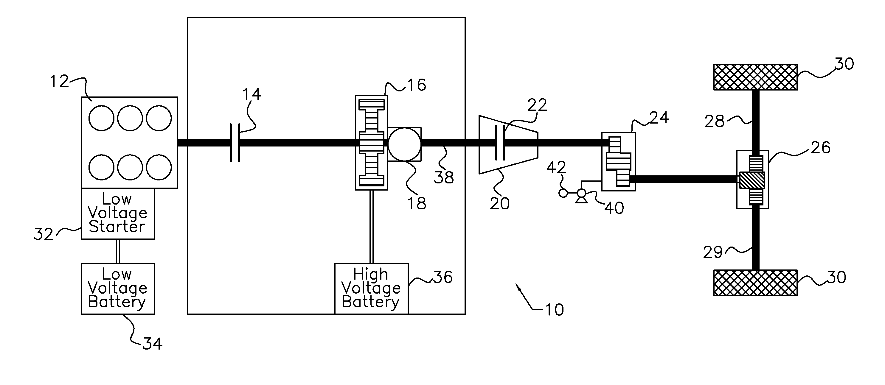
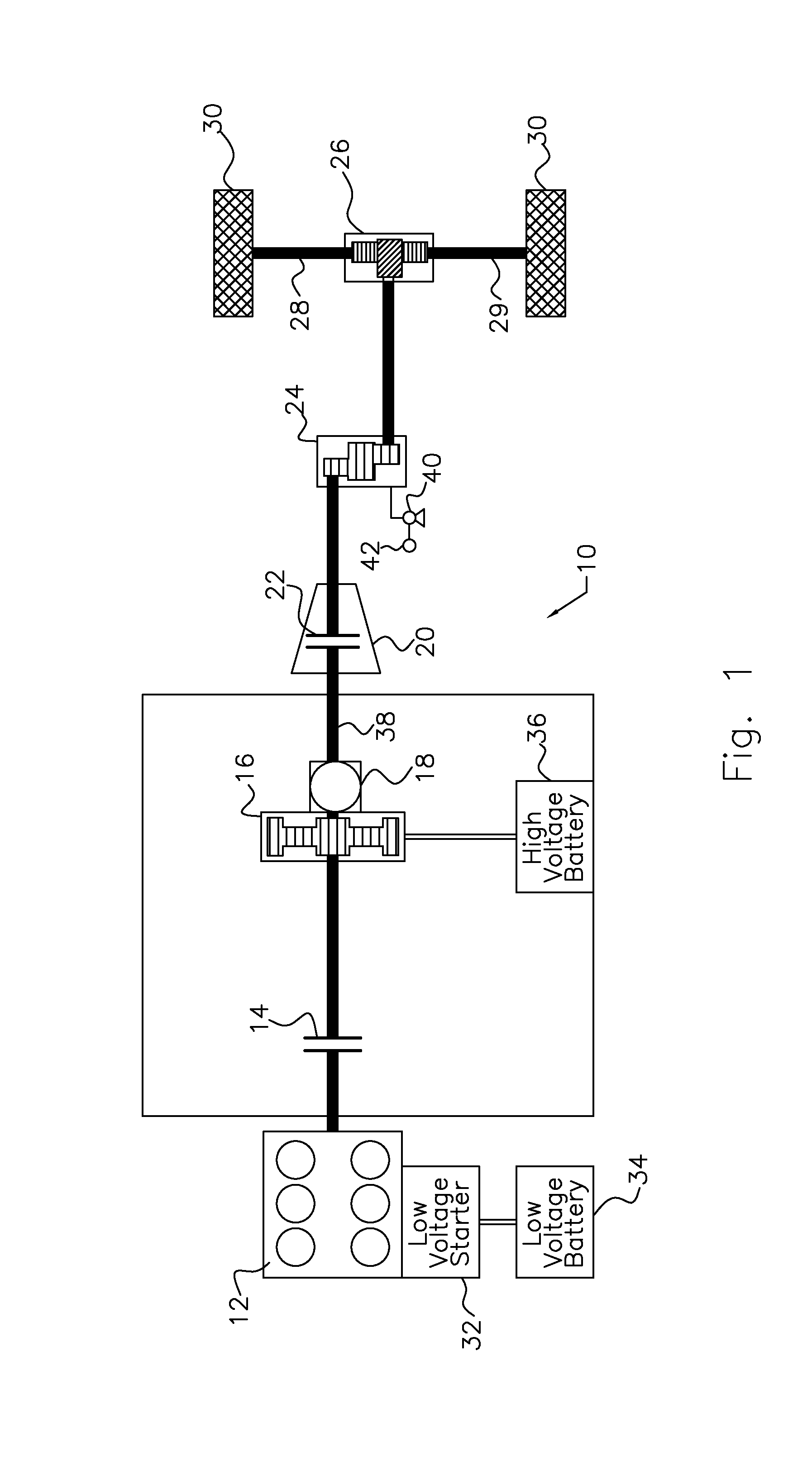
[0015]Referring first to FIG. 1, a hybrid electric powertrain 10 includes an internal combustion engine 12; engine disconnect clutch 14; electric machine or motor / generator 16; transmission hydraulic pump 18, i.e. a mechanical pump driven by the engine or electric machine or both of these; torque converter 20; torque converter lock-up clutch 22; transmission gearing 24; final drive gearing 26; shafts 28, 29; and driven wheels 30. A low voltage starter 32, powered by a low voltage battery 34, cranks the engine while starting the engine 12 and producing sustained combustion. A high voltage battery 36 powers the electric motor / generator 16.
[0016]The torque converter 20 is a hydraulic coupling that produces a hydrokinetic drive connection between an impeller, which is driveably connected to the engine 12 when clutch 14 is closed, and a turbine, which is driveably connected to the driven wheels 30.
[0017]The torque converter lock-up clutch 22 alternately opens and closes a drive connectio...
PUM
 Abstract
Description
Claims
Application Information