Method and apparatus for measuring a part

a technology for measuring parts and parts, applied in the direction of process and machine control, program control, instruments, etc., can solve the problems of significant inaccuracy in the measurement of parts, inability to separate 1sup>, and inability to measure the part accurately, so as to reduce the uncertainty of measurement and avoid systematic errors due to a single measurement direction of the prob

Active Publication Date: 2015-12-31
RENISHAW PLC
View PDF5 Cites 21 Cited by
  • Summary
  • Abstract
  • Description
  • Claims
  • Application Information

AI Technical Summary

Benefits of technology

[0018]The method enables a large number of “independent” measurements to be taken within a short time period relative to moving the part and/or contact probe once along a scan path and/or in a series of discrete movements. The cloud of measured points obtained at different positions of the part and contact probe in the machine may be analysed together on the assumption that errors for the points are uncorrelated and normally distributed. More specifically, measuring points that are closely located to each other on the part in substantially different locations in the machine volume may reduce measurement uncertainty because each measurement may be considered “independent” with few, if any, systematic errors common

Problems solved by technology

Errors in the measurement can result in inaccuracies in the generated representation.
It is also not possible to separate the 1st order circularity of the part from the axis centre drift or the off-centre error of the part.
Such a method may cancel out errors resulting from t

Method used


Image

  • Method and apparatus for measuring a part
  • Method and apparatus for measuring a part
  • Method and apparatus for measuring a part

Examples


Embodiment Construction

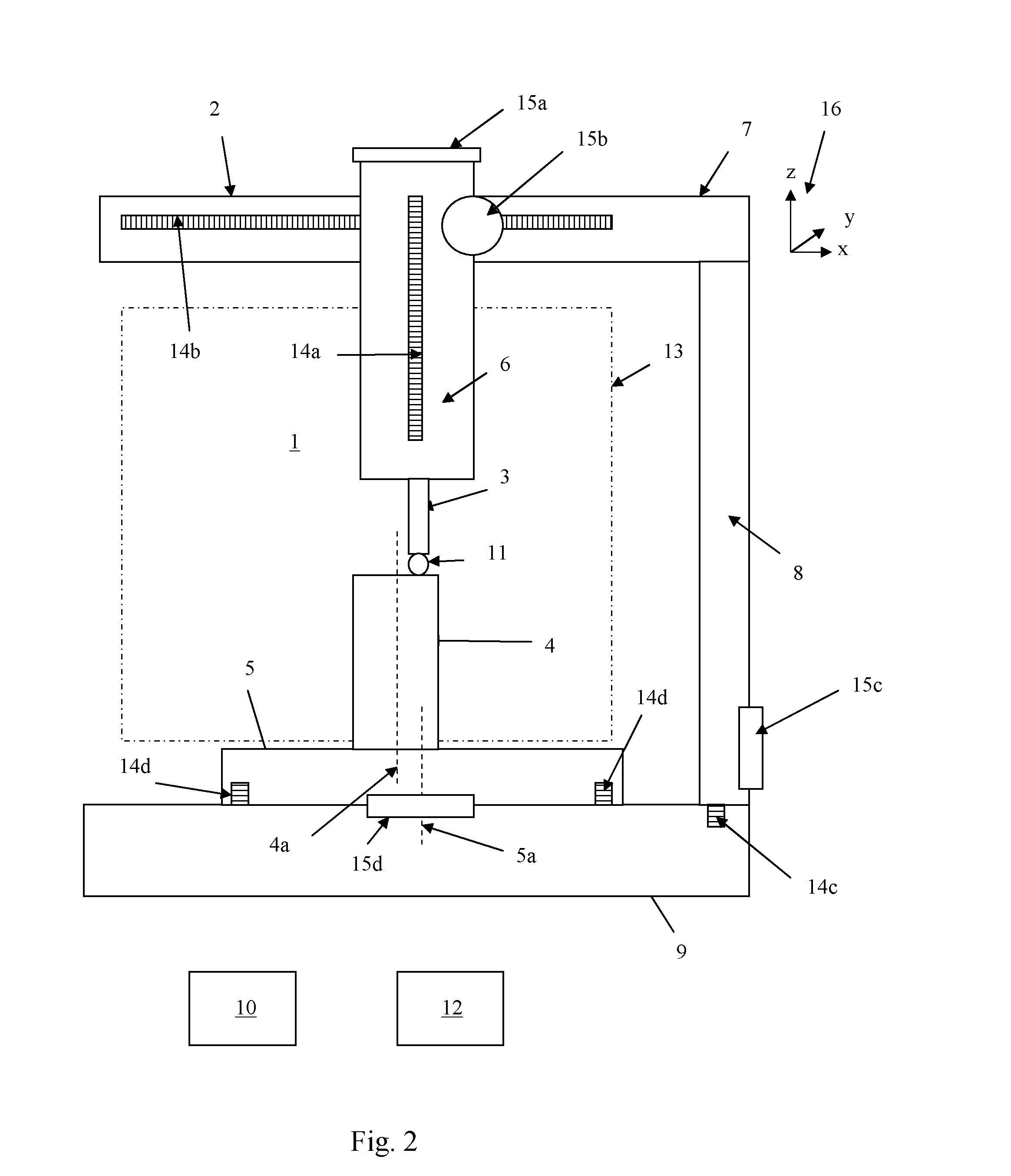
[0056]Referring to FIG. 2, a coordinate positioning machine 1 comprises a machine tool 2 and a contact probe 3, in this embodiment a multi-axis contact probe, mounted on the machine tool 2 for measuring a part 4. The machine tool comprises a rotary table 5 on which the part 4 can be mounted. The rotary table 5 comprises a rotary axis 5a The contact probe 3 is mounted to a quill 6 which is mounted on arms 7 and 8 such that the contact probe 3 can be moved in three linear directions, x, y and z relative to a base 9. The extent of movement of the probe 3 will be constrained by the construction of the machine tool 2 and may not extend across the entire volume of a part mounted in the machine tool 2. In this embodiment, the volume within which the probe 3 can move is indicated by dotted and dashed box 13.

[0057]Motors 15a, 15b, 15c, 15d move the rotary table 5, quill 6 and arms 7 and 8 under the control of controller 10, such as processor programmed with suitable software. Encoders 14a, 1...


PUM


Abstract

A method and apparatus for measuring a part with a contact probe mounted on a coordinate positioning machine. The method includes measuring a plurality of points on the part when both the part and contact probe are moving continuously between different positions within the coordinate positioning machine. The probe moves, relative to the part, along a scan path such that substantially coincident points that are closely located together along a curve or surface being measured are measured at relatively far apart positions in the machine and at relatively far apart positions along the scan path.

Description

FIELD OF INVENTION[0001]This invention concerns a method and apparatus for measuring a part. This invention has particular application to measuring a part using a coordinate positioning machine, such as a machine tool or coordinate measuring machine.BACKGROUND[0002]In machine tools, it is known to measure a part using a contact probe by moving a contact probe along a path such that the probe contacts a surface of the part at a number of points on the surface. A location of the points of contact can be determined from signals from the machine tool and contact probe and an appropriate shape fitted to these points to obtain a representation of the surface. It is also known to rotate the part with the contact probe fixed in position. Examples of these methods are described in U.S. Pat. No. 3,866,829.[0003]In U.S. Pat. No. 3,866,829, the contact probe is movable parallel to the rotational axis to take measurements at different heights on the part. However, it is also known to move the co...

Claims


Application Information

Patent Timeline
IPC IPC(8): G01B21/04
CPCG01B21/04G01B5/10G05B2219/37043G01B5/213G05B19/401G01B5/201
Inventor OULD, JOHN
Owner RENISHAW PLC
Why Eureka
Try Eureka