Calibration system and method of pulse power standard

A pulse power and calibration system technology, applied in the direction of measuring devices, instruments, measuring electrical variables, etc., can solve the problems of cumbersome testing process, pulse waveform distortion, and many testing steps, so as to reduce measurement uncertainty, improve efficiency and accuracy , The effect of simplifying the testing process

Active Publication Date: 2016-05-11
BEIJING INST OF RADIO METROLOGY & MEASUREMENT
View PDF6 Cites 9 Cited by
  • Summary
  • Abstract
  • Description
  • Claims
  • Application Information

AI Technical Summary

Problems solved by technology

[0004] However, due to the wide range of the signal spectrum under the radio frequency pulse condition, the electromagnetic field distribution, frequency response, and nonlinear effects of radio frequency circuits and devices make the calibration factor vary with the radio frequency, radio frequency pulse power and waveform. The test of the calibration factor requires a large amount of testing; especially during the test, there is likely to be a mismatch between the pulse power meter and the RF source in a wide frequency range, and the resulting signal reflection will affect the input to the calibrated pulse power meter. In addition, due to the distortion of the received pulse waveform due to transient effects, there will be a difference between the peak value of the pulse power obtained in the measurement and the peak value of the standard pulse power, and the pulse waveform will be distorted.
Therefore, it is difficult to accurately test the calibration factor
At the same time, the test process of the pulse power standard is cumbersome, the test time is long, the test steps are many, the test result data volume is huge, and the data analysis and processing are also relatively complicated, which requires computer automation to reduce the workload

Method used


Image

  • Calibration system and method of pulse power standard
  • Calibration system and method of pulse power standard
  • Calibration system and method of pulse power standard

Examples


Embodiment Construction

[0036] In order to achieve the purpose of the present invention, a pulse power standard calibration system and method are provided in the embodiments of the present invention. The purpose is to reduce the uncertainty of the calibration factor measurement when testing the calibration factor of the pulse power meter and improve the test efficiency and Data accuracy. The various embodiments of the present invention will be described in further detail below in conjunction with the accompanying drawings of the specification. Obviously, the described embodiments are only a part of the embodiments of the present invention, rather than all the embodiments. Based on the embodiments of the present invention, all other embodiments obtained by those of ordinary skill in the art without creative work shall fall within the protection scope of the present invention.

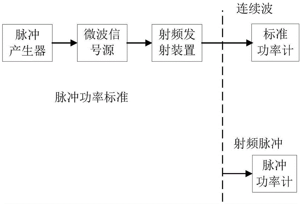
[0037] figure 1 It is a traditional pulse power standard method for pulse power meter calibration. The pulse power standard con...


PUM


Abstract

The invention provides a calibration system and method of a pulse power standard, and overcomes the problems such as pulse waveform distortion, and mismatching between a radio-frequency source and a power meter in a pulse power meter calibration factor testing process. In the calibration system of the pulse power standard, the pulse power standard is used for generating a radio-frequency signal, and a waveform analysis module analyzes a pulse envelope and calculates a waveform correction coefficient; a reflection analysis module tests and calculates a reflection coefficient; and a control and data handling module controls a radio-frequency pulse signal, collects test data, calculates a calibration factor, analyzes precision, and accesses data. The calibration method of the pulse power standard comprises the steps of: test condition control, waveform correction coefficient testing, reflection coefficient testing and power testing, calibration factor calculation, precision analysis and the like. By collecting, storing, analyzing and correcting the test data in real time, the measurement uncertainty is lowered, the test processing is simplified, the test efficiency is improved and the precision is improved.

Description

Technical field [0001] The present invention relates to the radio field, in particular to a system and method for pulse power testing. Background technique [0002] Pulse power is the basic measurement parameter of pulse signal, and pulse power meter is a meter for testing pulse power. In order to calibrate the pulse power meter, a pulse power standard is required. The pulse power standard consists of a microwave signal source, pulse generator, radio frequency transmitter, etc., used to generate radio frequency signals, including radio frequency pulse signals and continuous waves. [0003] To calibrate the pulse power meter is to determine the "calibration factor" of the pulse power meter being calibrated. It is easy to understand that if the standard radio frequency signal is input to the standard power meter and the calibrated pulse power meter, the calibration factor can be determined by comparing the difference between the indicated values ​​of the standard power meter and th...

Claims


Application Information

Patent Timeline
Patent Type & Authority Applications(China)
IPC IPC(8): G01R35/00
CPCG01R35/007
Inventor 侯海娇刘挺杨绪军
Owner BEIJING INST OF RADIO METROLOGY & MEASUREMENT
Why Eureka
Try Eureka