Restricted ball and socket joint for headset earcup

Active Publication Date: 2016-01-07
SONETICS HLDG LLC
View PDF2 Cites 18 Cited by
  • Summary
  • Abstract
  • Description
  • Claims
  • Application Information

AI Technical Summary

Problems solved by technology

A perennial problem in headset design is finding a way to make a mass-pr

Method used


Image

  • Restricted ball and socket joint for headset earcup
  • Restricted ball and socket joint for headset earcup
  • Restricted ball and socket joint for headset earcup

Examples


Embodiment Construction

[0054]As used and defined herein, the term “integral” means “of one piece with or, in an additional embodiment, assembled with”.

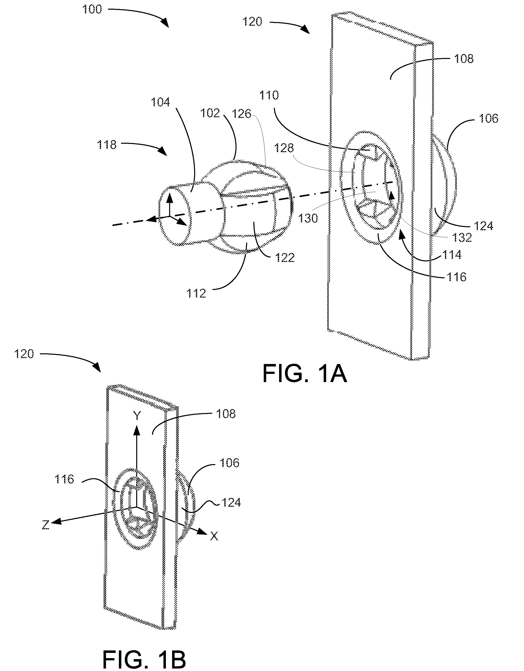
[0055]FIG. 1A is a perspective view illustrating an exemplary embodiment of the restricted ball and socket joint for headset ear cup 100, according to a preferred embodiment of the present invention. Irregular ball 118 is sized and shaped to be inserted into socket 120. Irregular ball 118 has a bulb 102 that has four axial grooves 112 (one of two visible of four labeled) circumferentially dispersed at even intervals and a stem 104, which will typically extend between the bulb 102 and another device (not shown in this view) which is integral (preferably of one piece) with the stem 104. Between grooves 112 on the bulb 102, a semi-spherical section 122 extends axially from the stem 104 to a truncated conical section 126. Irregular ball 118 is preferably made of a hard plastic with some resilience and is preferably made by injection molding. In various other em...


PUM


Abstract

A ball and socket joint preventing rotation of the ball about the axis of radial symmetry of the socket and restricting rotation of the ball about both axes orthogonal to the axis of radial symmetry to a predetermined angular value. The ball is irregular in shape and has grooves that receive ridges in the socket to accomplish the axial rotational restriction. The interaction of socket shape with ball shape accomplishes the rotational restrictions about the orthogonal axes. An exemplary use is for joining headset ear cups to headset side pieces to provide flexibility to accommodate a wide range of head shapes and sizes. The ball is preferably made of one piece with the headset side pieces and the socket is preferably made of one piece with the shell of the ear cup. Embodiments for head-mounted headsets and helmet-mounted headsets are disclosed.

Description

FIELD OF ART[0001]The present invention relates to a ball and socket joint specially adapted for use on a a hearing protection or communication headset ear cup. More particularly, the invention relates to a ball and socket joint limited to predetermined limits about the X and Y-axes and zero degrees about the Z-axis and in which the ball can be inserted or removed only by a Z-axis force.CROSS REFERENCE TO RELATED APPLICATIONS[0002]None.STATEMENT REGARDING FEDERALLY SPONSORED RESEARCH AND DEVELOPMENT[0003]None.BACKGROUND OF THE INVENTION[0004]Headsets are widely used in industry for hearing protection, electronic communication, or both. A perennial problem in headset design is finding a way to make a mass-production headset that will fit the wide variety of head sizes and shapes. Headset ear cups that are flexibly attached to headset side pieces must be resistant to disconnecting, have a simple and inexpensive connector, and provide a range of flexibility adequate to adapt to a wide ...

Claims


Application Information

Patent Timeline
IPC IPC(8): H04R1/10
CPCH04R1/1066H04R1/1008H04R1/1083H04R2201/023H04R2410/05
Inventor BROADLEY, SIMONVANDERPLOEG, BRIANTOOTHAKER, CALVIN
Owner SONETICS HLDG LLC
Why Eureka
Try Eureka