

Electrically actuated friction brake
a friction brake and electric actuator technology, applied in the direction of actuators, brake actuating mechanisms, axially engaging brakes, etc., can solve the problems of high cost pressure, overdimension, and inability to optimally utilize electric actuators, so as to reduce the attainable actuation time and keep the friction brake inexpensive
- Summary
- Abstract
- Description
- Claims
- Application Information
AI Technical Summary
Benefits of technology
Problems solved by technology
Method used
Image

Examples
Embodiment Construction
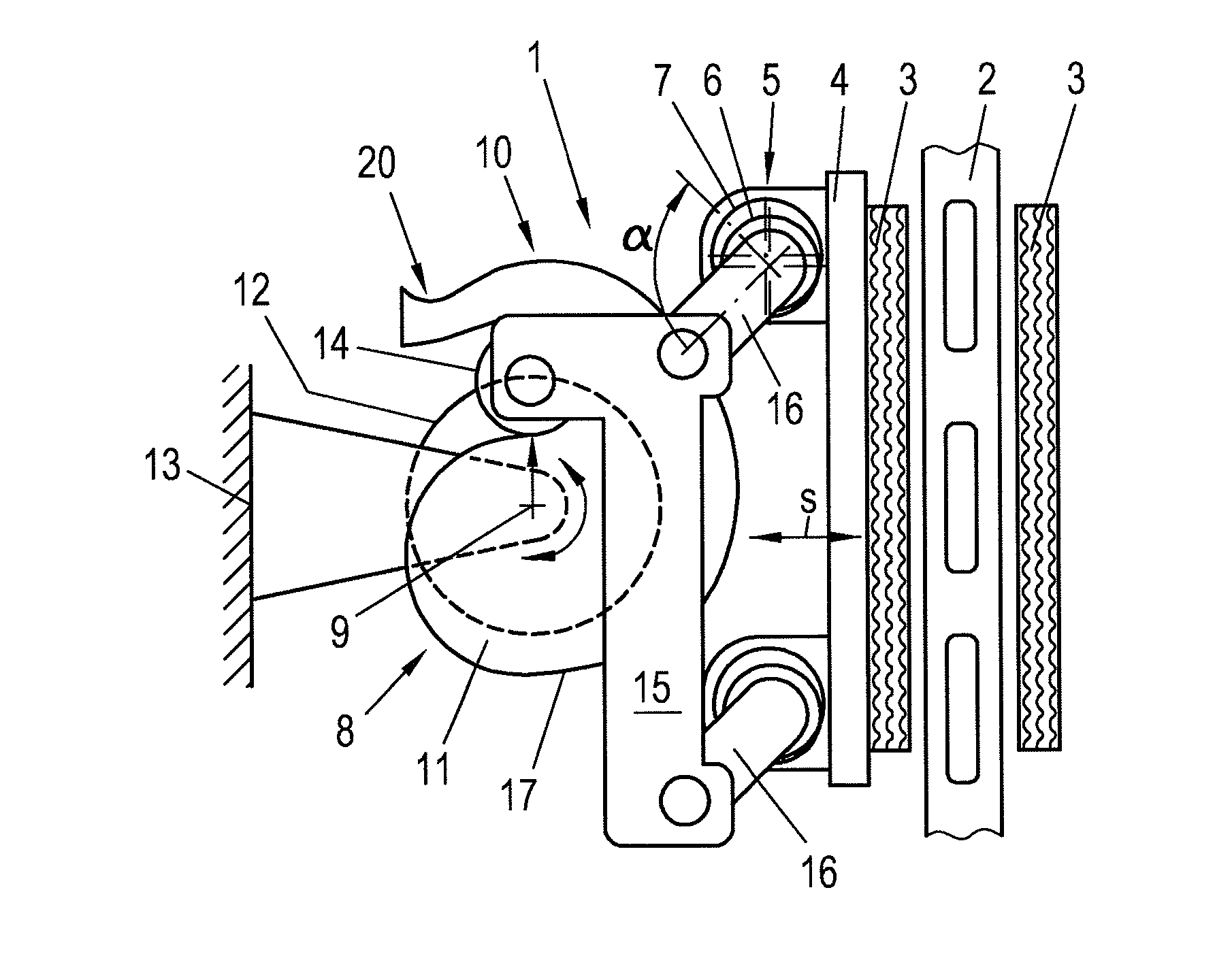
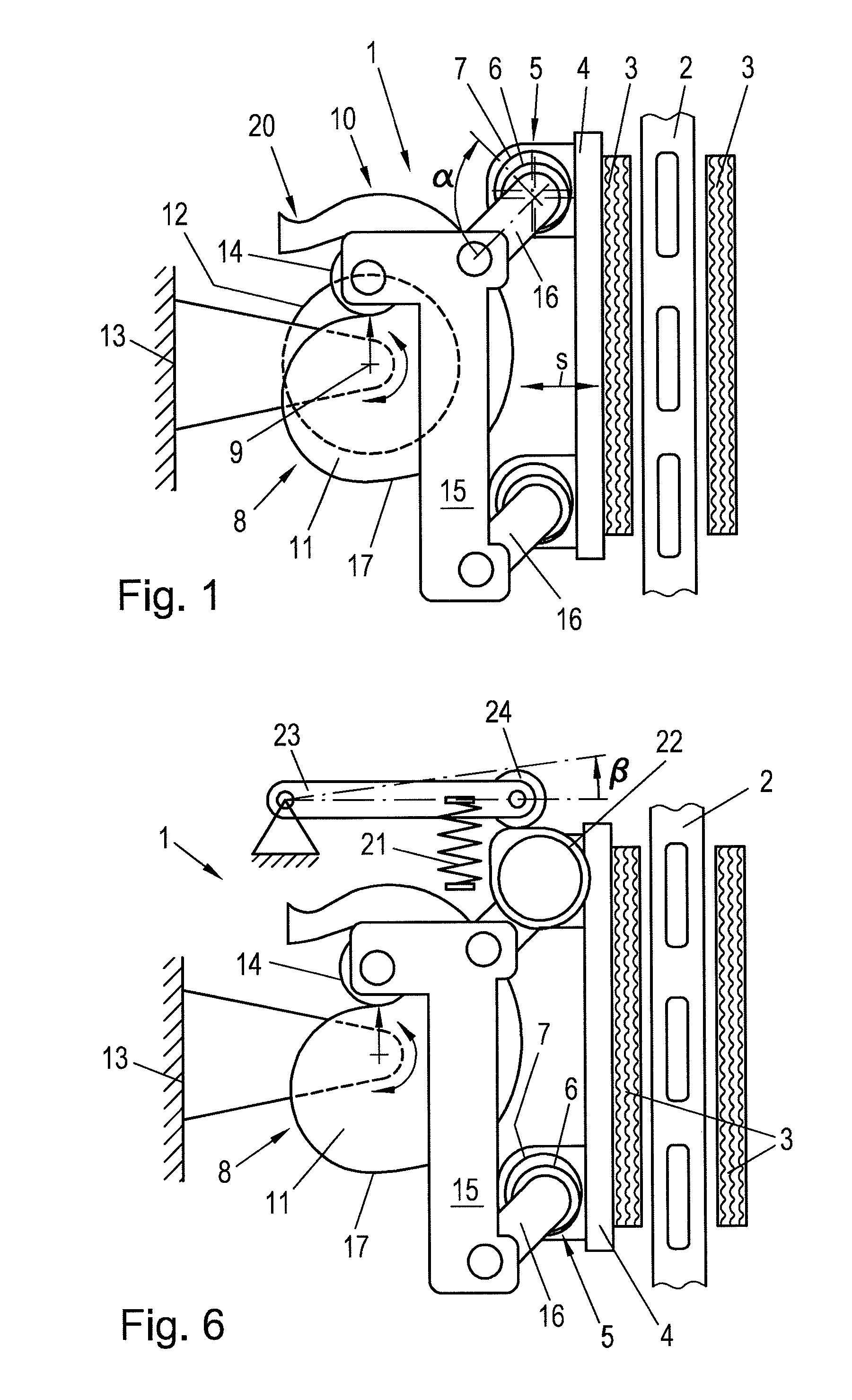
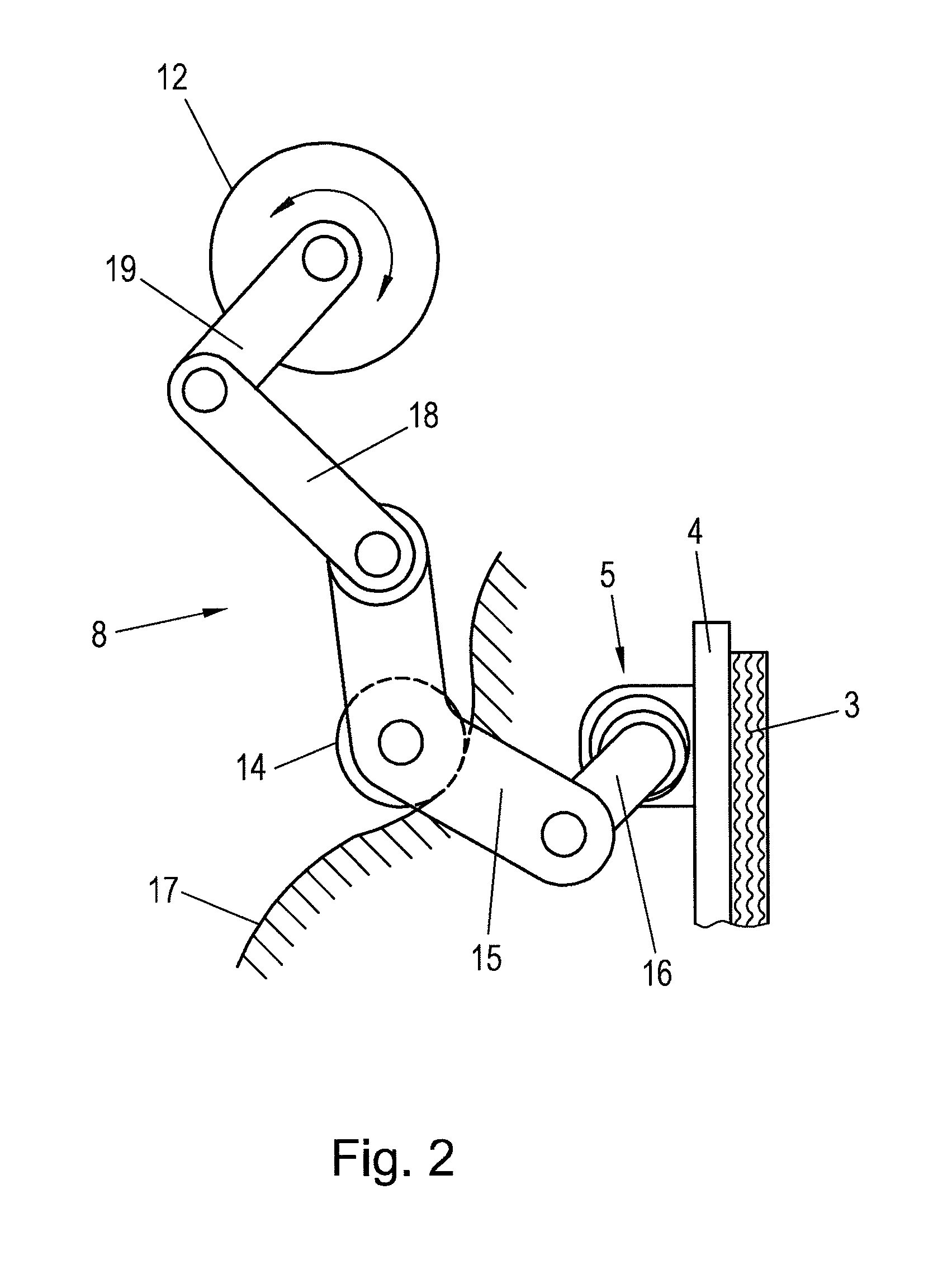
[0013]It is an object of the present invention to reduce the attainable actuation times of an electrically actuated friction brake and simultaneously to keep the friction brake inexpensive.
[0014]This object is achieved according to the invention through the provision of a second transmission element with an elevation curve and a coupling element provided on the first transmission element, wherein a follower element is arranged on the coupling element that follows the elevation curve under the action of the electrical actuator for actuating the first transmission element, wherein the second transmission element provides the input torque for the first transmission element and in that the input torques of the first transmission element over the rotational angle for different wear states of the brake pad result in an envelope curve and the input torque provided by the second transmission element over the rotational angle covers the range of the envelope curve. The second transmission el...
PUM
 Abstract
Description
Claims
Application Information