Damping valve

Active Publication Date: 2016-01-28
KYB CORP
View PDF0 Cites 36 Cited by
  • Summary
  • Abstract
  • Description
  • Claims
  • Application Information

AI Technical Summary

Benefits of technology

[0009]In view of the aforementioned problems, it is therefore an object of this invention to provide a damping valve capable of preventing an exc

Problems solved by technology

However, if the pressure boosting ratio increases, a damping force in a full soft setting increases disadvantageously.
Therefore, in the damping valve described above, as the damping force control range is widened, it is difficult to output a soft damping force, and the damping force becomes excessive, in particular, when a piston

Method used


Image

  • Damping valve
  • Damping valve
  • Damping valve

Examples


Embodiment Construction

[0019]A description will now be made for embodiments of this invention with reference to the accompanying drawings.

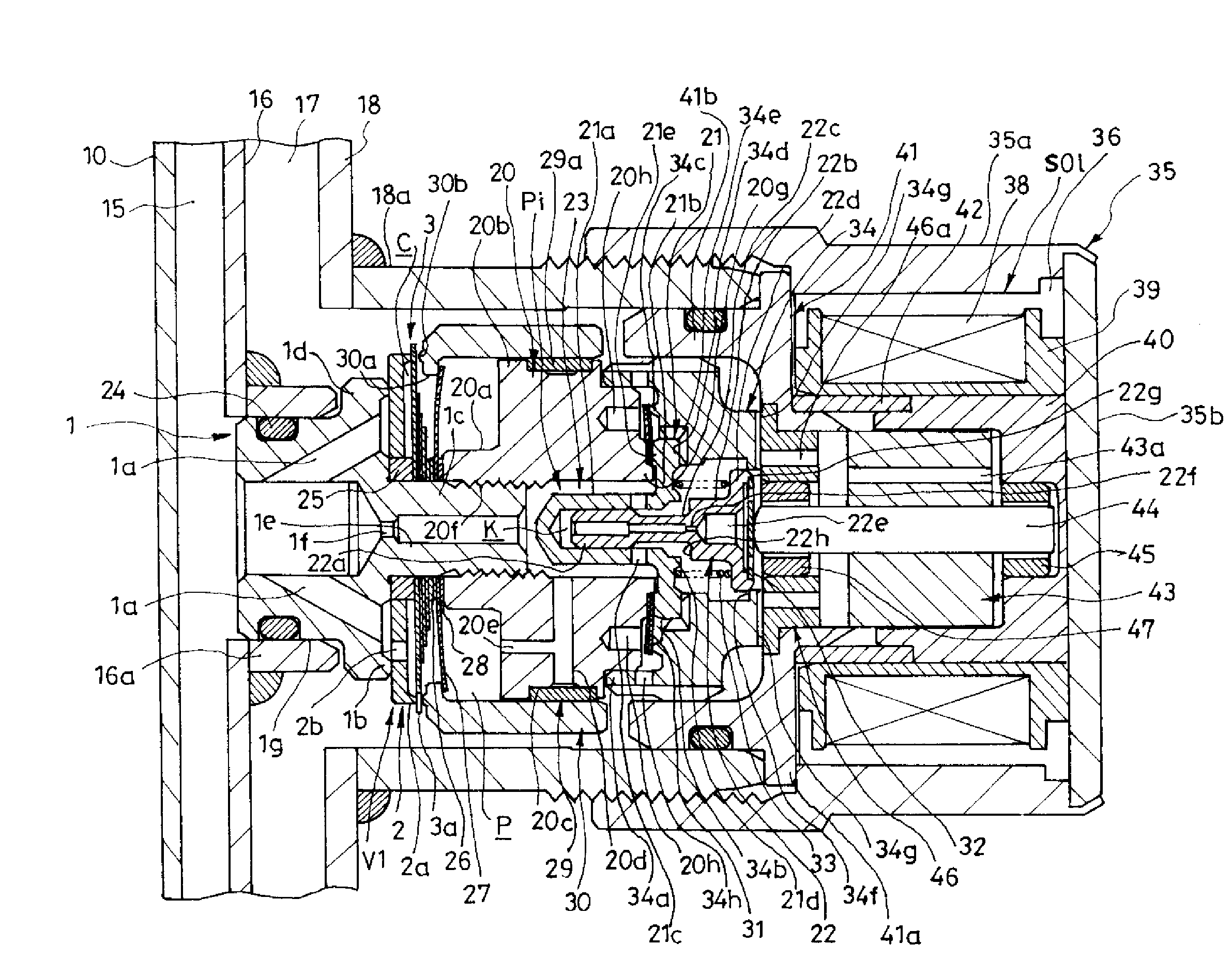
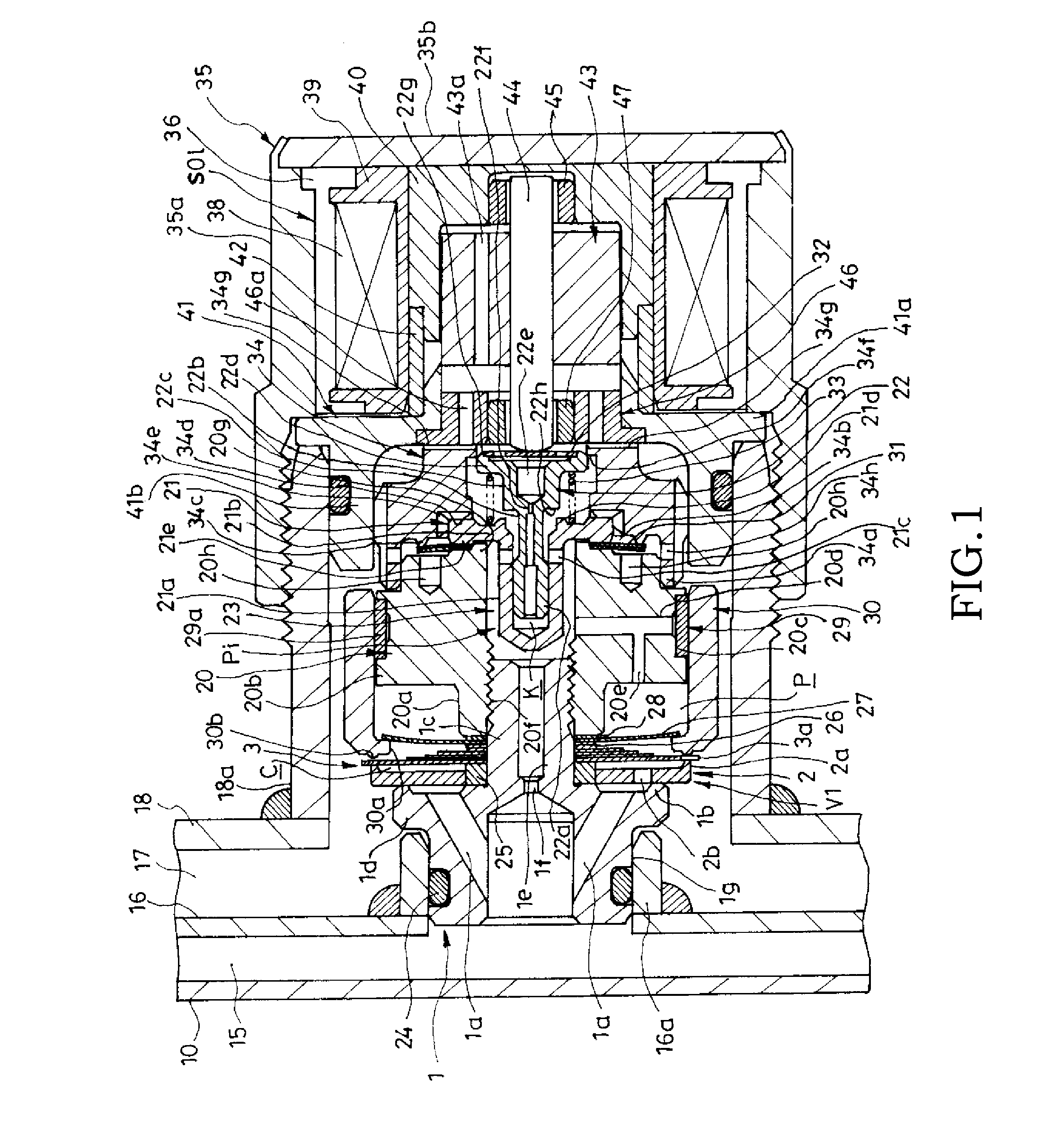
[0020]Referring to FIG. 1, a damping valve V1 includes a valve seat member 1 having a port 1a and a first valve seat 1b that surrounds the port 1a, a main valve body 2 that is seated on or unseated from the first valve seat 1b and has an annular second valve seat 2a provided oppositely to the valve seat member 1, a subsidiary valve body 3 seated on or unseated from the second valve seat 2a, a valve-body intermediate chamber C provided in an inner circumferential side of the second valve seat 2a between the main valve body 2 and the subsidiary valve body 3, a restrictive passage 2b that causes the valve-body intermediate chamber C and the port 1a to communicate with each other and applies resistance to a fluid flow, and a back-pressure chamber P as a subsidiary valve body biasing means for biasing the subsidiary valve body 3 toward the main valve body 2.

[0021]The damping...


PUM


Abstract

A damping valve includes a valve seat member having a port and a first valve seat surrounding the port, a main valve body seated on or unseated from the first valve seat, the main valve body having a second valve seat oppositely to the valve seat member, a subsidiary valve body seated on or unseated from the second valve seat, a valve-body intermediate chamber provided between the main valve body and the subsidiary valve body in an inner circumferential side of the second valve seat, a restrictive passage that causes the port and the valve-body intermediate chamber to communicate with each other, the restrictive passage being configured to apply resistance to a flow of fluid passing therethrough, and a subsidiary valve body biasing means configured to bias the subsidiary valve body toward the main valve body.

Description

TECHNICAL FIELD[0001]This invention relates to a damping valve.BACKGROUND ART[0002]There is known a type of damping valve, called a variable damping valve, capable of changing a damping force of a shock absorber interposed between a chassis and an axle of a vehicle. Such a type of damping valve includes, for example, an annular valve seat provided in the middle of a flow path connected from a cylinder of the shock absorber to a reservoir, a valve body seated on or unseated from the annular valve seat to open or close the flow path, a pilot passage branching from the flow path, an orifice provided in the middle of the pilot passage, a back-pressure chamber provided in the rear side of the valve body oppositely to the valve seat, a pilot valve provided downstream of the pilot passage, and a solenoid for adjusting a valve opening pressure of the pilot valve. In the variable damping valve, a secondary pressure downstream from the orifice in the pilot passage is introduced into the back-...

Claims


Application Information

Patent Timeline
IPC IPC(8): F16F9/34F16K1/36F16K1/42F16K27/02
CPCF16F9/34F16K27/02F16K1/42F16K1/36F16F9/348F16F9/46F16K17/02F16K17/04F16K31/06F16F9/325F16F9/464F16F9/465Y10T137/789
Inventor KAMAKURA, RYOSUKEMORI, TOSHIHIROABE, TOMOYASU
Owner KYB CORP
Why Eureka
Try Eureka