Electric shaver

a shaving device and electric technology, applied in the direction of metal working devices, etc., can solve the problems of less than desirable cutting effectiveness of conventional shaving devices, and achieve the effect of improving cutting effectiveness

Inactive Publication Date: 2016-02-04
RAYOVAC CORP
View PDF0 Cites 39 Cited by
  • Summary
  • Abstract
  • Description
  • Claims
  • Application Information

AI Technical Summary

Problems solved by technology

However, some conventional shavers have a less than desirable cutting effectiveness.

Method used


Image

  • Electric shaver
  • Electric shaver
  • Electric shaver

Examples


Embodiment Construction

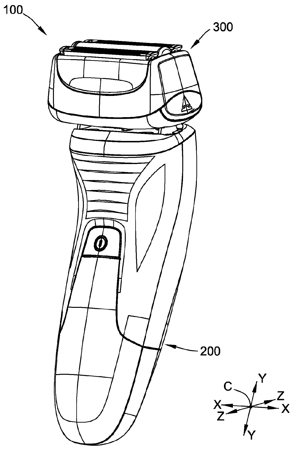
[0076]Referring now to the drawings, and in particular to FIG. 1, an electric shaver according to one embodiment is indicated generally by the reference numeral 100 and is illustrated in the form of an oscillating shaver (commonly referred to as a “foil shaver”) used for shaving hair from one's skin. It is understood, however, that elements of the shaver 100 may also be used on other suitable hair grooming devices (e.g., a rotary shaver, an epilator, a clipper, etc.) without departing from the scope of this invention. The illustrated shaver 100 comprises a handle, generally indicated at 200, and a head, generally indicated at 300, pivotably connected to the handle 200.

[0077]As shown in FIG. 1 and referred to throughout the following description, the shaver 100 has a width dimension along an axis X-X, a height dimension along an axis Y-Y, and a depth dimension along an axis Z-Z. These axes share a center C. As used herein, the terms “inner,”“inward,”“outer,”“outward,” and any variati...


PUM


Abstract

An electric shaver generally includes a handle and a head mounted on the handle. The head has at least three cutter assemblies arranged in a forward-rearward direction. The cutter assemblies include a forwardmost cutter assembly and a rearwardmost cutter assembly that are long hair cutter assemblies. Each of the long hair cutter assemblies has a substantially U-shaped upper blade and a lower blade in shearing contact with the upper blade. The cutter assemblies further include a short hair cutter assembly disposed between the long hair cutter assemblies.

Description

CROSS-REFERENCE TO RELATED APPLICATIONS[0001]This application claims priority to Provisional Patent Application Ser. No. 62 / 031,548, filed on Jul. 31, 2014, which is incorporated herein by reference in its entirety.BACKGROUND[0002]The present invention relates generally to grooming devices and, more particularly, to an electric shaver.[0003]Conventional electric shavers typically include a handle and a head attached to the handle. The head has a stationary blade and a movable blade that are arranged in sliding, face-to-face contact with one another. In operation, the movable blade is driven back and forth relative to the stationary blade as the head is moved over the skin in an area to be shaved. However, some conventional shavers have a less than desirable cutting effectiveness.[0004]There is a need, therefore, for an electric shaver with improved cutting effectiveness.SUMMARY[0005]In one embodiment, an electric shaver generally comprises a handle and a head mounted on the handle. ...

Claims


Application Information

Patent Timeline
Patent Type & Authority Applications(United States)
IPC IPC(8): B26B19/10B26B19/38
CPCB26B19/3846B26B19/10B26B19/12B26B19/14B26B19/3813B26B19/386
Inventor PROVOLO, DANIEL JOHNMAGUIRE, RICHARD KIRKTETEAK, DANIEL RICHARDSCHNEIDER, PAUL ANTHONYXUAN, WANGWONG, JOHN Y.M.
Owner RAYOVAC CORP
Why Eureka
Try Eureka