Manufacturing method of bus bar unit

Inactive Publication Date: 2016-02-04
KYB CORP
View PDF2 Cites 27 Cited by
  • Summary
  • Abstract
  • Description
  • Claims
  • Application Information

AI Technical Summary

Benefits of technology

[0006]It is an object of the present invention to provide a manufacturing method of the bus bar u

Problems solved by technology

In the above-described conventional bus bar unit, a large force is applied to the respective bus bars due to a pressure

Method used


Image

  • Manufacturing method of bus bar unit
  • Manufacturing method of bus bar unit
  • Manufacturing method of bus bar unit

Examples


Embodiment Construction

[0030]With reference to the drawings, an embodiment of the present invention will be described.

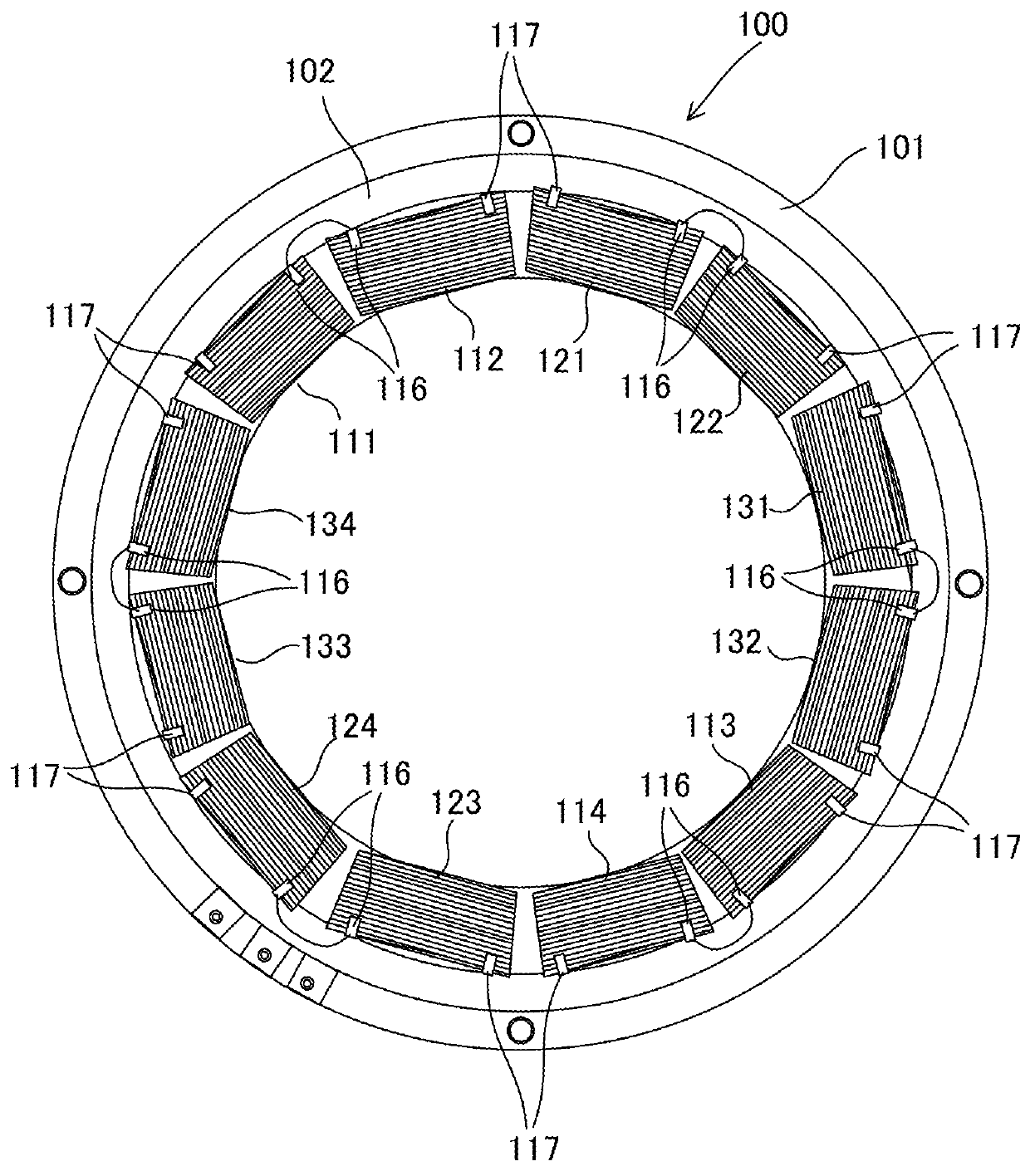
[0031]FIG. 1 is a structure diagram illustrating a stator 100 that forms a three phase AC motor.

[0032]A plurality of teeth, which are not illustrated, are formed on an annular-shaped stator core 102 that is held in a housing 101 in such a manner that the teeth project toward the inner periphery side. Copper wires are wound around the teeth to form coils 111 to 114, 121 to 124, and 131 to 134.

[0033]On the stator core 102, twelve coils in total, that is, U-phase coils 111 to 114, V-phase coils 121 to 124, and W-phase coils 131 to 134 are disposed annularly along the circumferential direction of the stator 100.

[0034]A first U-phase coil 111 and an adjacent second U-phase coil 112 are arranged opposingly to a third U-phase coil 113 and an adjacent fourth U-phase coil 114. Further, a first V-phase coil 121 and an adjacent second V-phase coil 122 are arranged opposingly to a third V-phase coil 1...


PUM


Abstract

A manufacturing method of a bus bar unit includes: a primary setting step of disposing a part of a plurality of bus bars into a first mold; a primary molding step of performing an insert molding by injecting the insulating resin material into the first mold, so as to form a primary molded member having a step part; a secondary setting step of disposing the primary molded member and a remaining bus bar of the plurality of bus bars into a second mold; and a secondary molding step of performing the insert molding by injecting the insulating resin material into the second mold, so as to form the bus bar unit. In the secondary setting step, the primary molded member and the remaining bus bar of the plurality of bus bars are arranged in the second mold in such a manner that at least one of an outer periphery and an inner periphery of the remaining bus bar abuts against the step part of the primary molded member.

Description


Claims


Application Information

Patent Timeline
Owner KYB CORP
Why Eureka
Try Eureka