Wheel chair with urinal device

Inactive Publication Date: 2016-02-11
YAO JEN HUO +4
View PDF5 Cites 12 Cited by
  • Summary
  • Abstract
  • Description
  • Claims
  • Application Information

AI Technical Summary

Benefits of technology

[0014]The present invention will become more obvious from the following description when taken in connection with the accompa

Problems solved by technology

All of the prior art disclosed are not designed for being cooperated with a wheel chair which allows

Method used


Image

  • Wheel chair with urinal device
  • Wheel chair with urinal device
  • Wheel chair with urinal device

Examples


Embodiment Construction

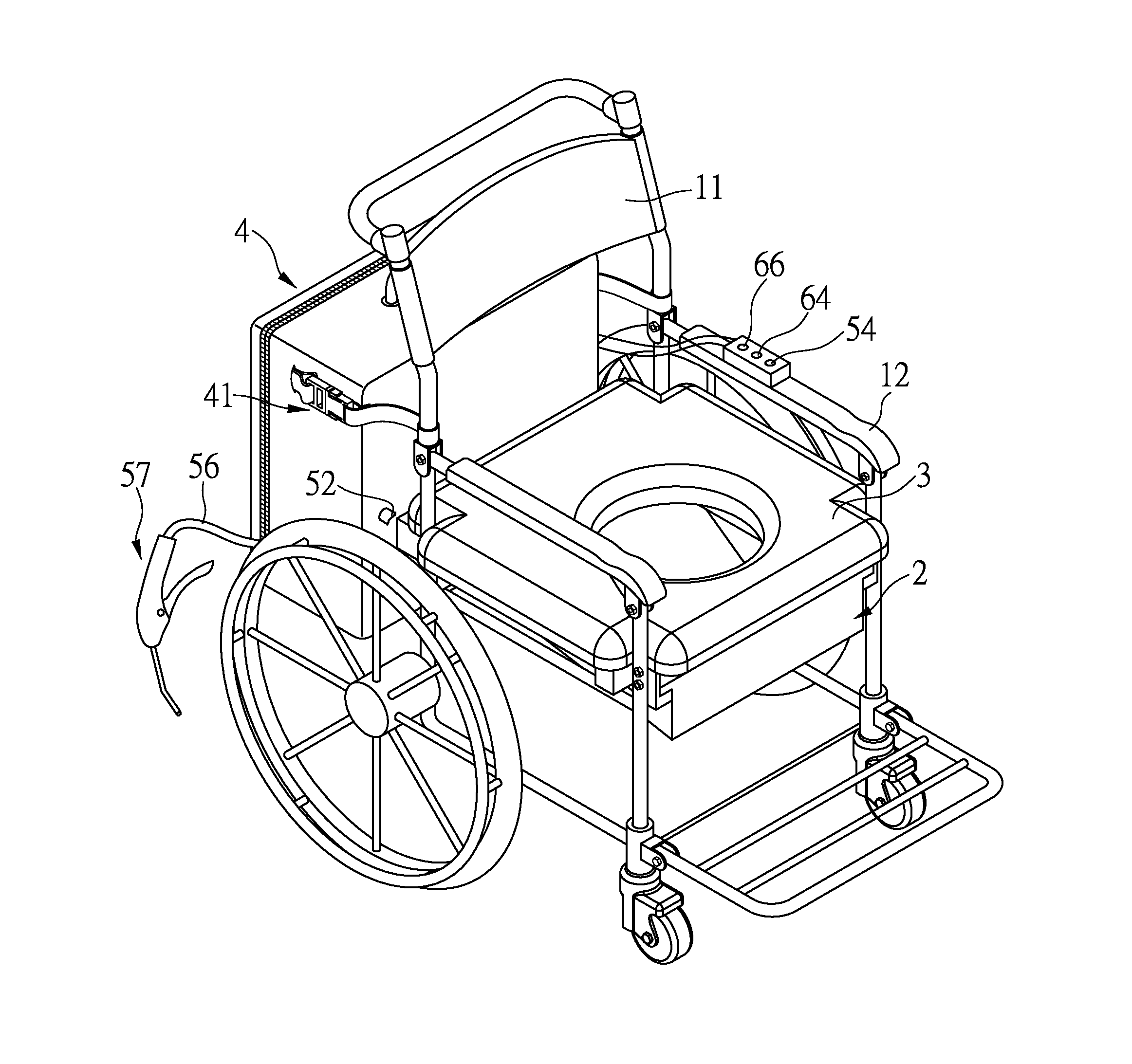
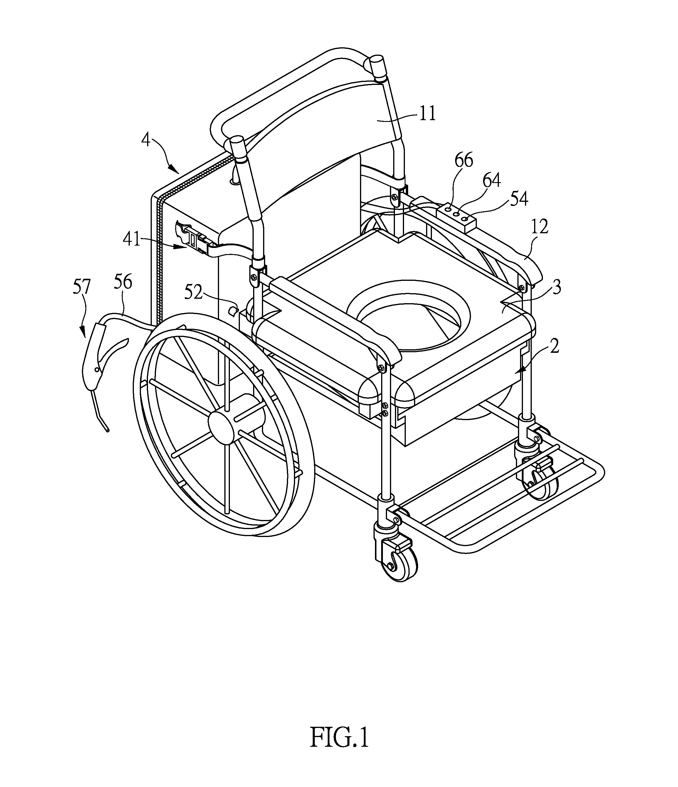
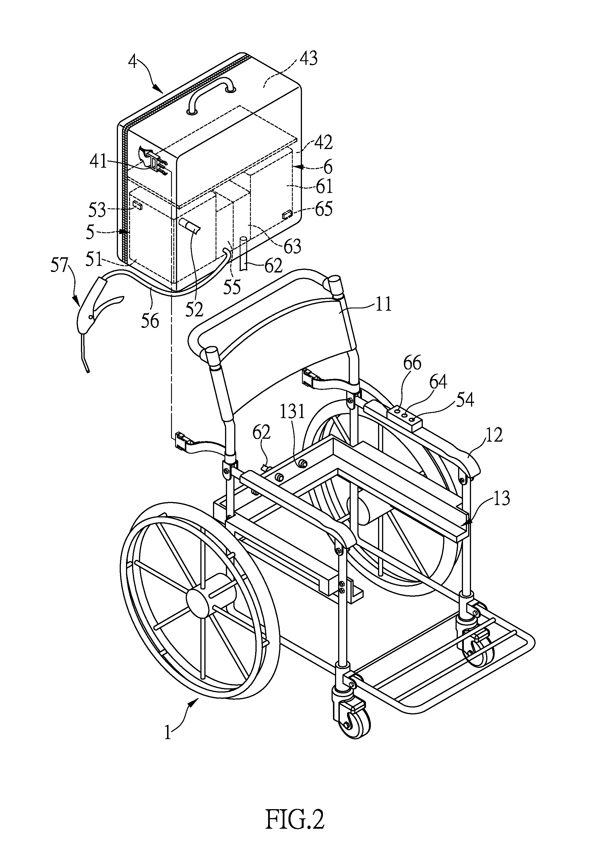
[0020]Referring to FIGS. 1 to 5, the wheel chair with urinal device of the present invention comprises a wheel chair 1 which comprises two side parts and each side part is connected with a rear wheel and a front wheel. A support frame is connected between the two side parts. A backrest 11 is connected between the two rear ends of the two side parts, and a handle is connected to the backrest 11. The support frame includes a U-shaped upright wall which has two sidewalls and a rear sidewall. Each of the two sidewalls and the rear sidewall has a horizontal flange extending therefrom. A cushion 3 is supported on the horizontal flanges and has a hole 31 defined therethrough. Multiple outlets 131 are defined through the rear sidewall of the support frame.

[0021]A drain pan 2 is removably located beneath the cushion 3 and has a slanted bottom wall 21 which has a higher rear end and a lower front end. A drain hole is defined through the slanted bottom wall 21 and located at the lower front en...


PUM


Abstract

A wheel chair with urinal device includes a wheel chair a cushion connected thereto and the cushion has a hole. A drain pan with a slanted bottom wall is removably located beneath the cushion and a drain hole is defined through the lower front end of the slanted bottom wall. Multiple outlets defined in the support frame communicate with the space above the slanted bottom wall. A box is removably attached to the rear side of the backrest and has a collection unit and a cleaning unit received therein. The cleaning unit provides detergent to clean and flush the waste in the drain pan and collected in the collection unit. The user activates and controls the cleaning unit by operating a cleaning switch on the armrest.

Description

BACKGROUND OF THE INVENTION[0001]1. Fields of the Invention[0002]The present invention relates to a Continuation-In-Part application of applicant's former U.S. patent application Ser. No. 13 / 902,986, filed on May 28, 2013.[0003]2. Descriptions of Related Art[0004]The conventional bodily waste reception devices or the like known to applicant are respectively disclosed in U.S. Pat. No. 3,383,713, U.S. Pub. No. 2005 / 0060797, and U.S. Pub. No. 2007 / 0044222. All of the prior art disclosed are not designed for being cooperated with a wheel chair which allows the user to move from one place to another while the urinal device is still available and easily used.[0005]The present invention intends to provide a wheel chair with urinal device to eliminate the shortcomings mentioned above.SUMMARY OF THE INVENTION[0006]The present invention relates to a wheel chair with urinal device, and comprises a wheel chair having a backrest and a support frame which supports a cushion therein. The cushion h...

Claims


Application Information

Patent Timeline
IPC IPC(8): A61G5/10A61G5/12
CPCA61G5/1002A61G2005/125A61G2005/122A61G5/12A47K11/04A61G9/006E03D5/00A61G2203/12
Inventor YAO, JEN-HUOYAO, LIANG-CHUYAO, HSIAO-CHANGYAO, ZAI-FUYAO, CHIH-MIN
Owner YAO JEN HUO
Why Eureka
Try Eureka