Braking apparatus of vehicle

Active Publication Date: 2016-02-25
MITSUBISHI MOTORS CORP
View PDF2 Cites 14 Cited by
  • Summary
  • Abstract
  • Description
  • Claims
  • Application Information

AI Technical Summary

Benefits of technology

The present invention is about a braking system for vehicles that reduces fluctuations in braking force during automatic braking for collision avoidance. This system prevents fluctuations in the vehicle's deceleration rate, which can make the driver feel uncomfortable and cause variations in braking distance. By using only friction brakes and avoiding regenerative braking during automatic braking, this system reduces these fluctuations and improves the driver's experience.

Problems solved by technology

In the vehicle equipped with a collision avoidance device, a regenerative brake device and a friction brake device like the one disclosed in the above patent publication, if the battery becomes fully charged, for example, while both the regenerative braking and the friction braking are executed during the automatic braking for collision avoidance, electricity cannot be supplied to the battery any longer, with the result that the regenerative braking terminates.
Thus, because of the termination of the regenerative braking, the braking force and, as a consequence, the rate of deceleration of the vehicle fluctuate during the automatic braking, causing a feeling of strangeness and possibly increasing variation in the braking distance.

Method used


Image

  • Braking apparatus of vehicle
  • Braking apparatus of vehicle
  • Braking apparatus of vehicle

Examples


Embodiment Construction

[0016]An embodiment of the present invention will be described below with reference to the drawings.

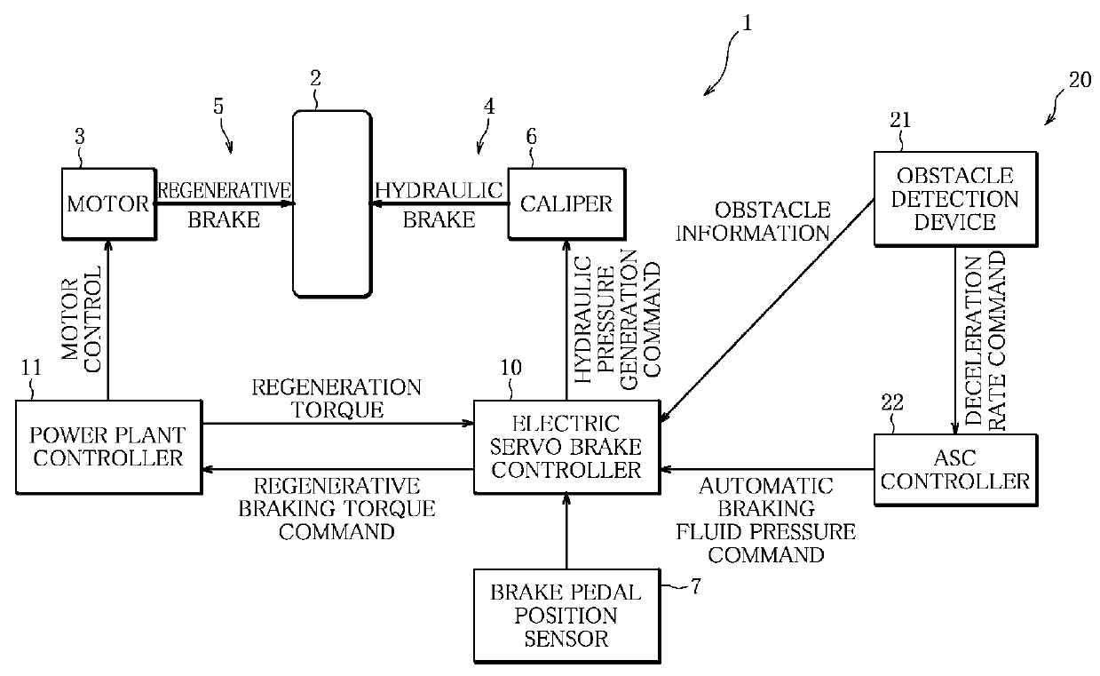
[0017]FIG. 1 illustrates a schematic configuration of a vehicle braking apparatus 1 according to the embodiment of the present invention. Referring to the figure, the configuration of the braking apparatus 1 will be described below.

[0018]The braking apparatus 1 of the embodiment is mounted on a vehicle whose drive wheel 2 is driven by a motor 3 (electric motor), such as an electric vehicle, hybrid vehicle or plug-in hybrid vehicle.

[0019]Operation of the motor 3 is controlled by a power plant controller 11, and electric power is supplied to the motor 3 from a drive battery, not shown, mounted on the vehicle to drive the motor 3.

[0020]As shown in FIG. 1, the vehicle braking apparatus 1 includes a hydraulic (oil) brake device 4 (friction brake device) associated with each of wheels including the drive wheel 2, and a regenerative brake device 5 (regenerative brake device) which generates ...


PUM


Abstract

A braking apparatus 1 of a vehicle includes: a hydraulic brake device 4 that brakes the vehicle via friction in response to operation of a brake pedal; a regenerative brake device 5 that performs regenerative braking using, as an electricity generator, a motor 3 for running the vehicle; and a collision avoidance device 20 that performs automatic braking of the vehicle by controlling operation of the hydraulic brake device 4 in accordance with obstacle detection information detected by an obstacle detection device 21, to avoid collision of the vehicle with an obstacle, wherein an electric servo brake controller 10 of the collision avoidance device 20 terminates activation of the regenerative braking, if activated, before the automatic braking is started by the collision avoidance device 20.

Description

BACKGROUND OF THE INVENTION[0001]1. Field of the Invention[0002]The present invention relates to a braking apparatus of a vehicle equipped with a regenerative brake device and a friction brake device, and more particularly, to techniques of controlling braking force when automatic braking is executed by a collision avoidance device.[0003]2. Description of the Related Art[0004]A vehicle equipped with an electric motor for running the vehicle, such as an electric vehicle or hybrid vehicle, is conventionally provided with a regenerative brake device that uses the electric motor as an electricity generator when the vehicle is decelerating or running down a slope, to convert deceleration energy into electric energy to charge a battery mounted on the vehicle.[0005]Such a vehicle equipped with a regenerative brake device is provided further with a friction brake device that brakes .the vehicle by frictional force in response to operation of a brake pedal, like a hydraulic brake device.[000...

Claims


Application Information

Patent Timeline
IPC IPC(8): B60L7/26B60T7/22
CPCB60L7/26B60T7/22B60T1/10B60T2201/022B60T2270/604B60L3/0015B60L7/12B60L7/18B60L15/2009B60T13/586B60L2240/12B60L2240/421B60L2240/423B60L2240/80B60L2250/26Y02T10/72Y02T10/64Y02T10/70
Inventor NAKASO, HIROYUKIHAYASHIKAWA, KAZUFUMI
Owner MITSUBISHI MOTORS CORP
Why Eureka
Try Eureka