Exposure apparatus, exposure method, and exposure system

Inactive Publication Date: 2007-08-16
CANON KK
View PDF10 Cites 10 Cited by
  • Summary
  • Abstract
  • Description
  • Claims
  • Application Information

AI Technical Summary

Benefits of technology

[0011] The present invention is directed to an exposure apparatus that reduces a fluctuation of the liquid's transmittance.

Problems solved by technology

However, as a result of a comparison between pure water and the HRI liquid, this inventor has discovered that the immersion exposure apparatus that uses the HRI liquid poses the following problems different from the immersion exposure apparatus that uses the pure water:
The first problem about the immersion exposure apparatus that uses the HRI liquid is a necessity of a recycle of the liquid because the HRI liquid is more expensive than pure water and more influential to the environment.
However, studies by this inventor have revealed that this detector cannot precisely detect the purity of the liquid.
In other words, the conventional immersion exposure apparatus cannot well guarantee that the circulated or recycled liquid has good quality, and may recycle liquid that is too inferior to recycle.
This is a peculiar problem to the immersion exposure apparatus that uses the HRI liquid to circulate the high quality liquid, and is irrelevant to the immersion exposure apparatus that uses pure water.
The second problem that uses the HRI liquid is that the HRI liquid's transmittance is likely to degrade.
Although the conventional immersion exposure apparatus includes a degassing unit that reduces all dissolved gases to restrain gas bubbles, the degassing unit cannot well eliminate dissolved oxygen, and a small amount of dissolved oxygen residue reduces the liquid's transmittance.
In addition, it is feared that a reaction, such as decomposition due to the exposure light causes a drop of the transmittance.
As the liquid's transmittance reduces, its temperature rises due to the absorption of the exposure light and its refractive index changes, causing the exposure aberration.

Method used


Image

  • Exposure apparatus, exposure method, and exposure system
  • Exposure apparatus, exposure method, and exposure system
  • Exposure apparatus, exposure method, and exposure system

Examples


first embodiment

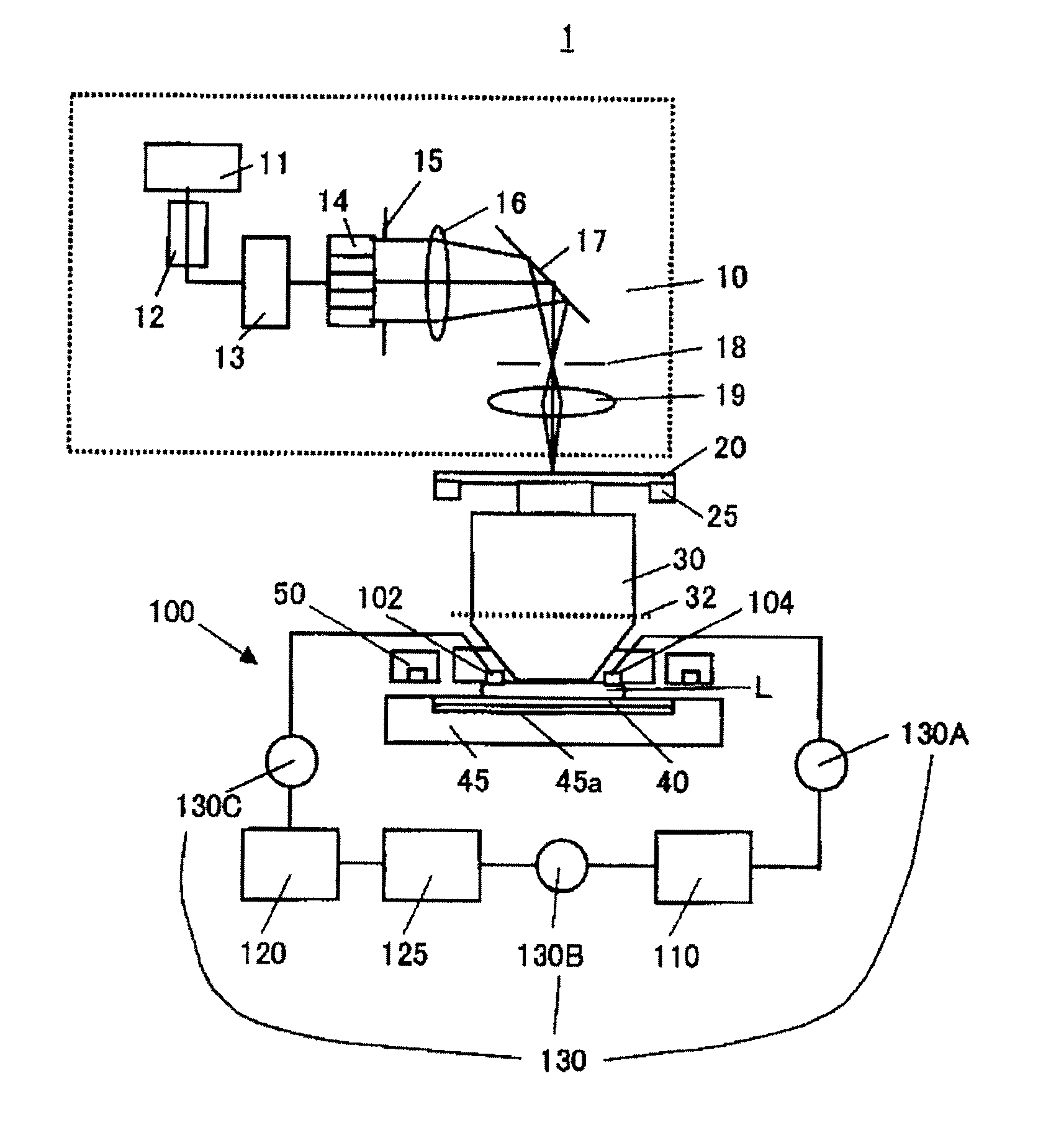
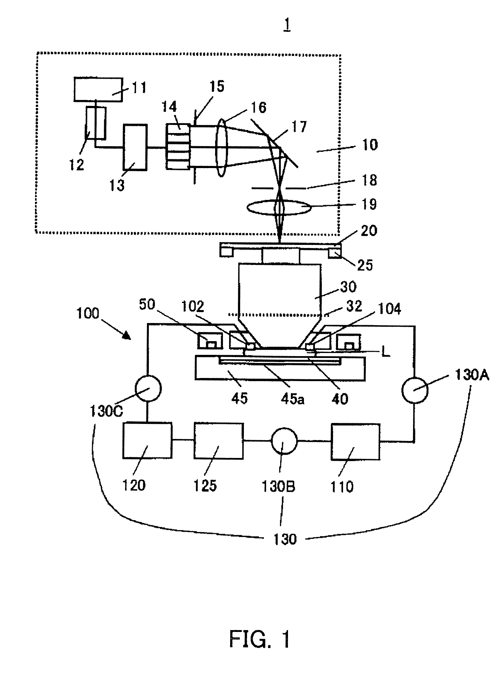
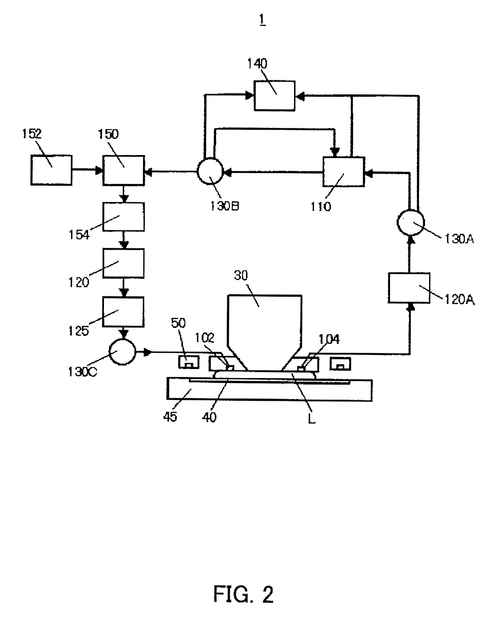
[0061] The circulator 100 of a first embodiment includes, as shown in FIG. 3, a nitrogen bubbler (oxygen removal unit) 120, and a degassing filter (degassing unit) 125. FIG. 3 is a partial block diagram showing part of a structure of the exposure apparatus 1.

[0062] The exposure apparatus 1 of the first embodiment uses hydrocarbonaceous HRI liquid having a refractive index of 1.64 for the liquid L to be supplied to the space between the projection optical system 30 and the wafer 40.

[0063] The atmosphere around the exposure position in the exposure apparatus 1 is replaced with nitrogen by the oxygen diluter 50, but a small amount of oxygen that dissolves in the liquid L reduces the transmittance of the liquid L. The dissolved oxygen concentration in the liquid L that is measured just before the exposure position is below 0.1 ppm when both the nitrogen bubbler 120 and the degassing filter 125 work. The dissolved oxygen concentration in the liquid L that is measured just before the ex...

second embodiment

[0064] Similar to FIG. 3 in the first embodiment, the circulator 100 of the second embodiment has the bubbler (oxygen removal unit) 120 and the degassing filter (degassing unit) 125, although the bubbler uses helium.

[0065] The exposure apparatus 1 of a second embodiment uses hydrocarbonaceous HRI liquid having a refractive index of 1.64 for the liquid L that is supplied to the space between the projection optical system 30 and the wafer 40.

[0066] The environment around the exposure position in the exposure apparatus 1 is replaced with nitrogen by the oxygen diluter 50, but a small amount of oxygen that dissolves in the liquid L lowers the transmittance of the liquid L. The dissolved oxygen concentration in the liquid L that is measured just before the exposure position is below 0.1 ppm when both the helium bubbler 120 and the degassing filter 125 work. The dissolved oxygen concentration in the liquid L that is measured just before the exposure position is 2 ppm when the helium bub...

third embodiment

[0067] As shown in FIG. 4, the circulator 100 of a third embodiment includes the oxygen removal unit 120, and the degassing unit 125, and further includes the measurement unit 130A between the purifier 110 and the exposure position used to expose the wafer 40. FIG. 4 is a partial block diagram that shows part of the structure of the exposure apparatus 1.

[0068] The exposure apparatus 1 of the third embodiment uses hydrocarbonaceous HRI liquid having a refractive index of 1.64 for the liquid L that is supplied to the space between the projection optical system 30 and the wafer 40.

[0069] In the exposure position of the exposure apparatus 1, the liquid L contacts the final lens of the projection optical system 30, wafer 40, the top plate of the wafer stage 45, and surrounding air, and its transmittance lowers. In particular, the photoresist is applied onto the wafer 40, and a material, such as the residue solvent in the photoresist, photoacid generator, and base, mixes in the liquid L...


PUM


Abstract

An exposure apparatus has a projection optical system configured to project an image of a reticle pattern onto a substrate, and exposes the substrate via liquid supplied to a space between the substrate and the projection optical system. The exposure apparatus includes an oxygen removal unit configured to reduce dissolved oxygen in the liquid by bringing the liquid into contact with a gas other than oxygen, and a degassing unit configured to reduce a dissolved gas in the liquid.

Description

BACKGROUND OF THE INVENTION [0001] The present invention relates to an exposure apparatus, an exposure method, and an exposure system. [0002] A conventional reduction projection exposure apparatus projects a circuit pattern of a reticle (mask) onto a wafer or another substrate via a projection optical system in manufacturing fine devices, such as a semiconductor memory and a logic circuit, using the photolithography technology. [0003] The minimum critical dimension (“CD”) (or a resolution) transferable by the reduction projection exposure apparatus is proportionate to a wavelength of the light used for exposure, and inversely proportionate to the numerical aperture (“NA”) of the projection optical system. The shorter the wavelength is and the higher the NA is, the smaller the resolution is. Along with the recent demand for the fine processing to a semiconductor device, use of a shorter wavelength of the exposure light is promoted. For example, use of the ultraviolet (“UV”) light hav...

Claims


Application Information

Patent Timeline
IPC IPC(8): G03B27/42
CPCG03F7/70925G03F7/70341G03F7/20
Inventor SAKAI, KEITA
Owner CANON KK
Why Eureka
Try Eureka