Woodworking Lathe Adjustment Structure

a technology of adjustment structure and woodworking lathe, which is applied in the direction of woodworking machinery, manufacturing tools, wood-turning machines, etc., can solve the problems of poor accuracy and increase the cos

Active Publication Date: 2016-04-14
KINGSAND MACHINERY
View PDF0 Cites 1 Cited by
  • Summary
  • Abstract
  • Description
  • Claims
  • Application Information

AI Technical Summary

Benefits of technology

[0011]In order to achieve the aforesaid objective, the woodworking lathe adjustment structure of the present invention comprises a base having an axial slide trough thereon, a head unit and a tail unit disposed on the base. An adjustment block is provided between the head unit/the tail unit and the slide trough. Two sides of the adjustment block ha...

Problems solved by technology

This results in that the head and tail units are not coaxial to cause an error...

Method used


Image

  • Woodworking Lathe Adjustment Structure
  • Woodworking Lathe Adjustment Structure
  • Woodworking Lathe Adjustment Structure

Examples


Embodiment Construction

[0024]Embodiments of the present invention will now be described, by way of example only, with reference to the accompanying drawings.

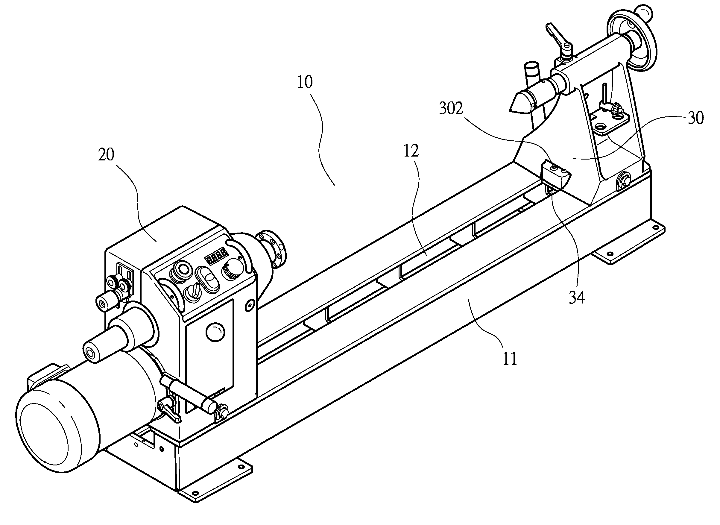
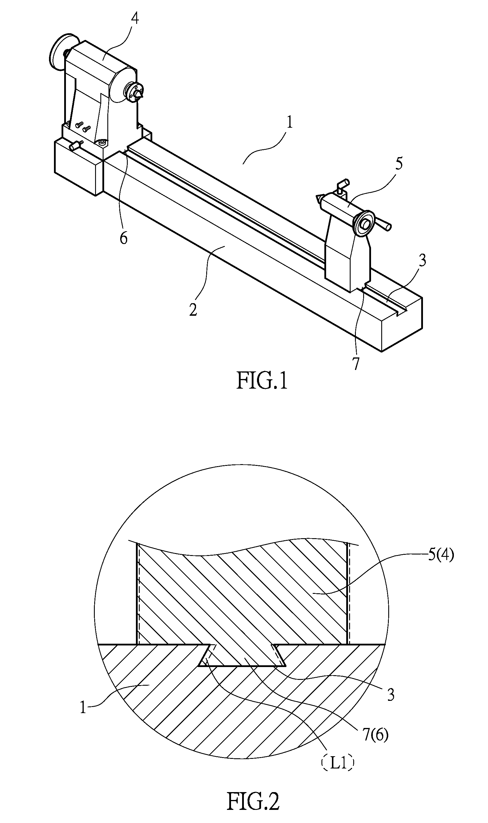
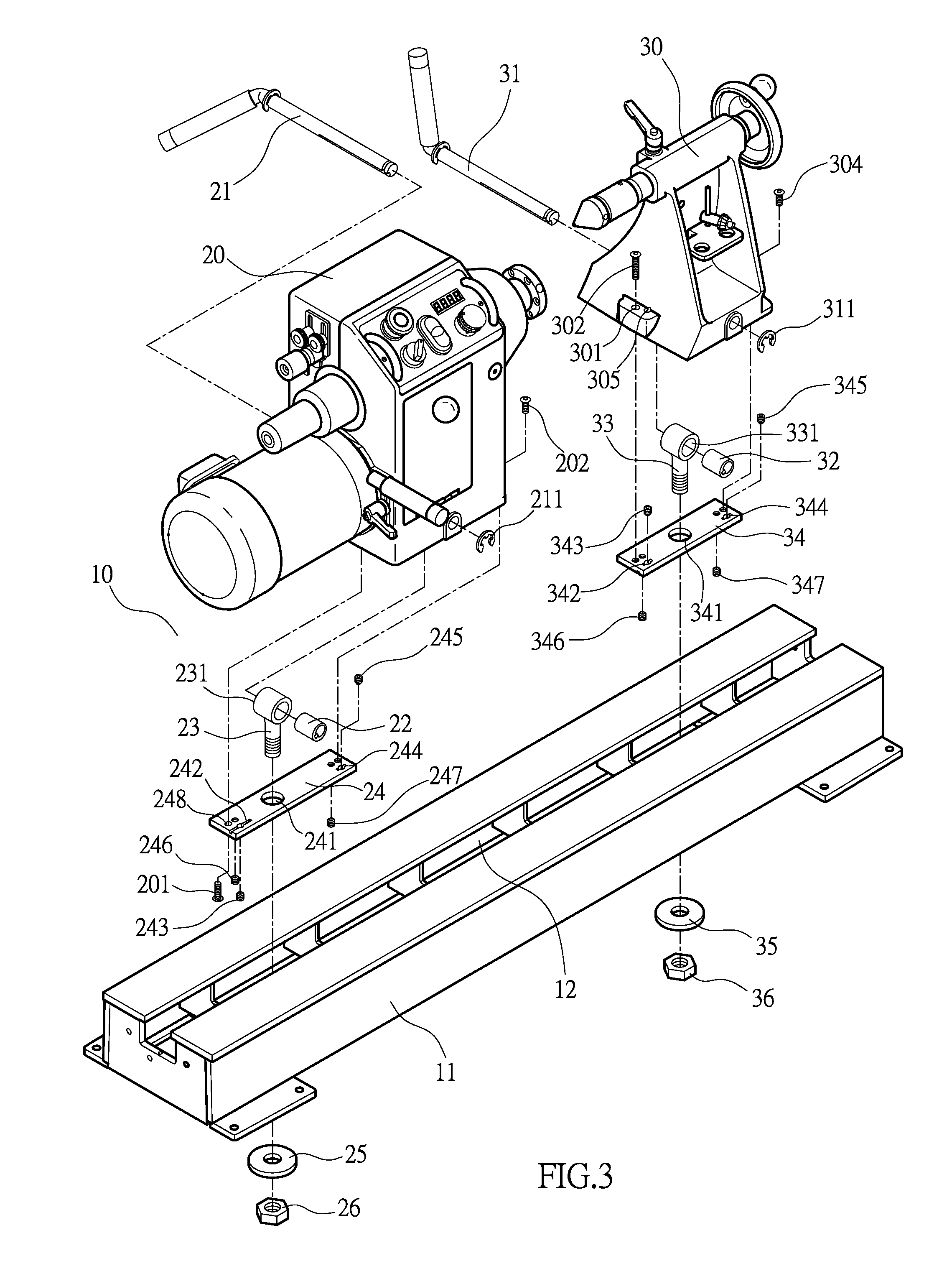
[0025]Referring to FIGS. 3, 4, 5, 6, 10, the present invention comprises a machine 10. The machine 10 comprises a base 11 having an axial slide trough 12 thereon. A head unit 20 and a tail unit 30 are disposed on the base 11. The head unit 20 and the tail unit 30 are movable along the rail trough 12 of the base 11. An adjustment block 24, 34 is provided between the head unit 20 / the tail unit 30 and the slide trough 12. Two sides of the adjustment block 24, 34 have grooves 242, 244, 342, 344, respectively. Each of the grooves 242, 244, 342, 344 has a compelling hole 2421, 2441, 3421, 3441 therein. The compelling hole 2421, 2441, 3421, 3441 has a threaded section 2422, 2442, 3422, 3442 and a non-threaded section 2423, 2443, 3423, 3443 therein. The compelling hole 2421, 2441, 3421, 3441 is provided with a space adjustment bolt 243, 245, 343, 345 therein....


PUM


Abstract

A woodworking lathe adjustment structure includes a base having an axial slide trough thereon, a head unit and a tail unit disposed on the base. An adjustment block is provided between the head unit/the tail unit and the slide trough. The adjustment block includes a groove, a space adjustment bolt, and an adjustment bolt. The groove has a compelling hole therein. The compelling hole has a threaded section and a non-threaded section therein. The space adjustment bolt is screwed to the threaded section. The adjustment block is secured to the bottom of the head unit/the tail unit by fixing bolts, respectively, and inserted in the slide trough. When the space adjustment bolt passes the non-threaded section of the compelling hole, the sides of the groove will be deformed outward and curvedly to offset a gap which is caused by wear and tear of the adjustment block and the slide trough.

Description

NOTICE OF COPYRIGHT[0001]A portion of the disclosure of this patent document contains material which is subject to copyright protection. The copyright owner has no objection to any reproduction by anyone of the patent disclosure, as it appears in the United States Patent and Trademark Office patent files or records, but otherwise reserves all copyright rights whatsoever.BACKGROUND OF THE PRESENT INVENTION[0002]1. Field of Invention[0003]The present invention relates to a woodworking lathe adjustment structure, and more particularly to a woodworking lathe adjustment structure able to offset the gap between a head unit / a tail unit and a slide trough and to adjust the central axis of the head and tail units to enhance the accuracy of woodworking process.[0004]2. Description of Related Arts[0005]As shown in FIG. 1 and FIG. 2, a conventional woodworking lathe comprises a machine 1. The machine 1 comprises a base 2 having an axial dovetail trough 3, a heat unit 4 and a tail unit 5 dispose...

Claims


Application Information

Patent Timeline
IPC IPC(8): B27C7/00
CPCB27C7/00B27C7/04
Inventor CHANG, CHIN-FENG
Owner KINGSAND MACHINERY
Why Eureka
Try Eureka