Portable Cantilevered Table
a cantilevered table and cantilever technology, applied in the direction of secondary cell charging/discharging, wall tables, suspending tables, etc., can solve the problems of inability to accommodate objects, table is likely to be tilted or swaying, and cannot be used to support objects, etc., to achieve rapid and easy mounting and dismounting
- Summary
- Abstract
- Description
- Claims
- Application Information
AI Technical Summary
Benefits of technology
Problems solved by technology
Method used
Image

Examples
first embodiment
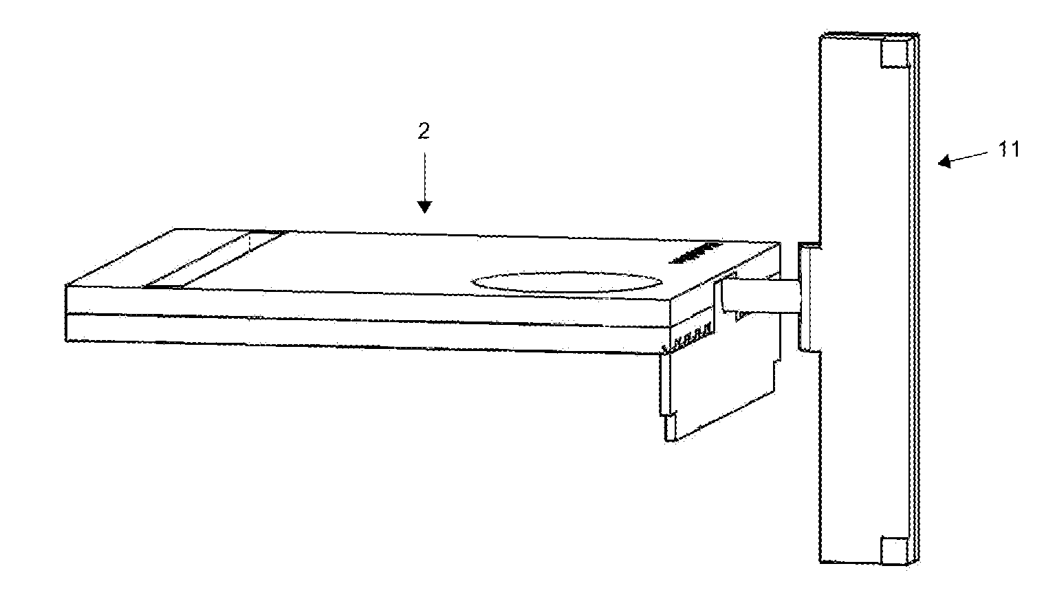
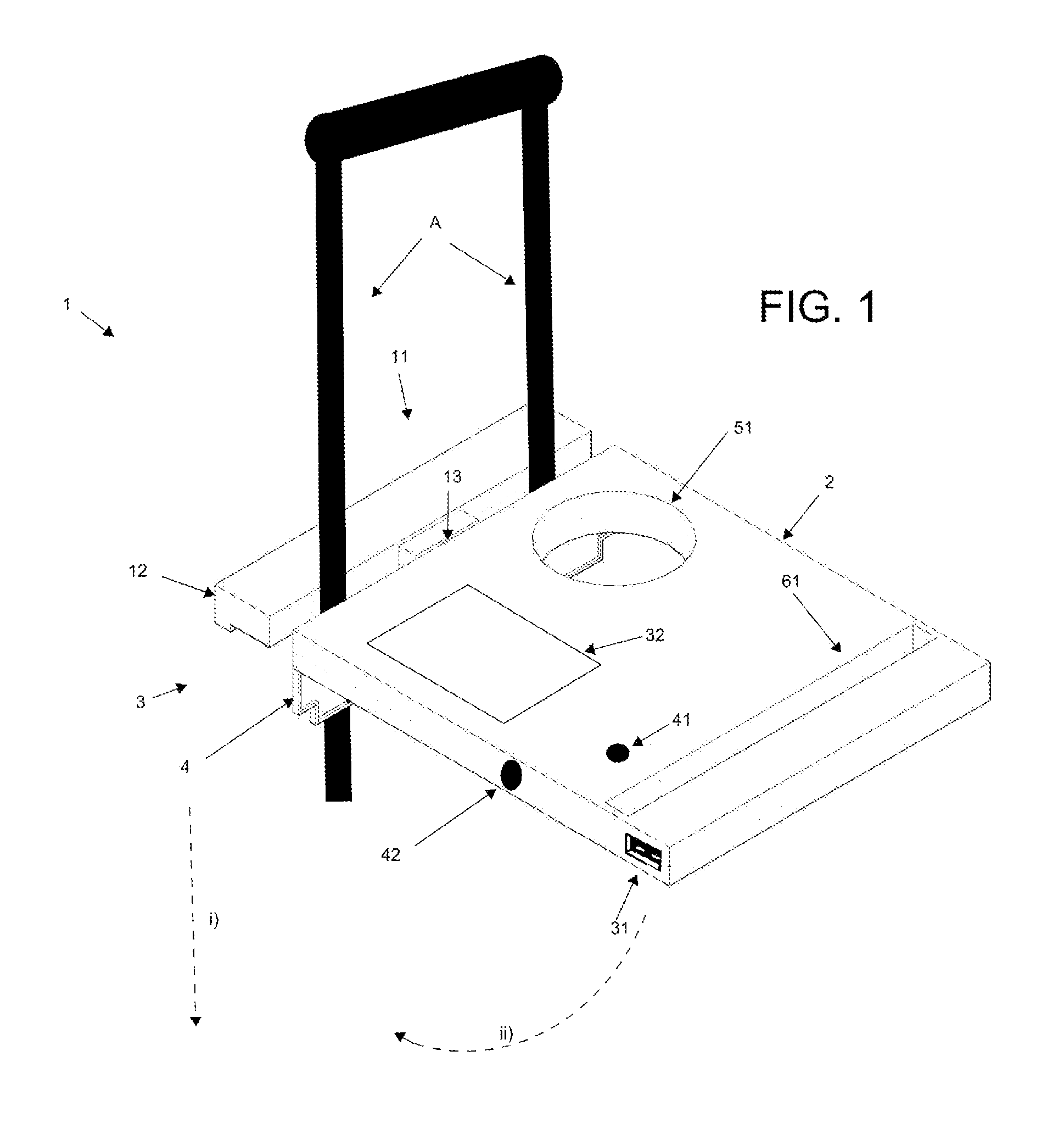
[0030]In a first preferred embodiment of this invention, illustrated by way of example in FIG. 1, the portable cantilevered table 1 of the invention is shown engaged on the two upright rods A of a piece of roll-aboard luggage, the suitcase portion of which is not illustrated. This table comprises a tabular body 2, the proximal end of which being the end that will be closest to the user when in use, and the distal end being that which will furthest away from the user, which is the end shown making contact with the upright rods A.
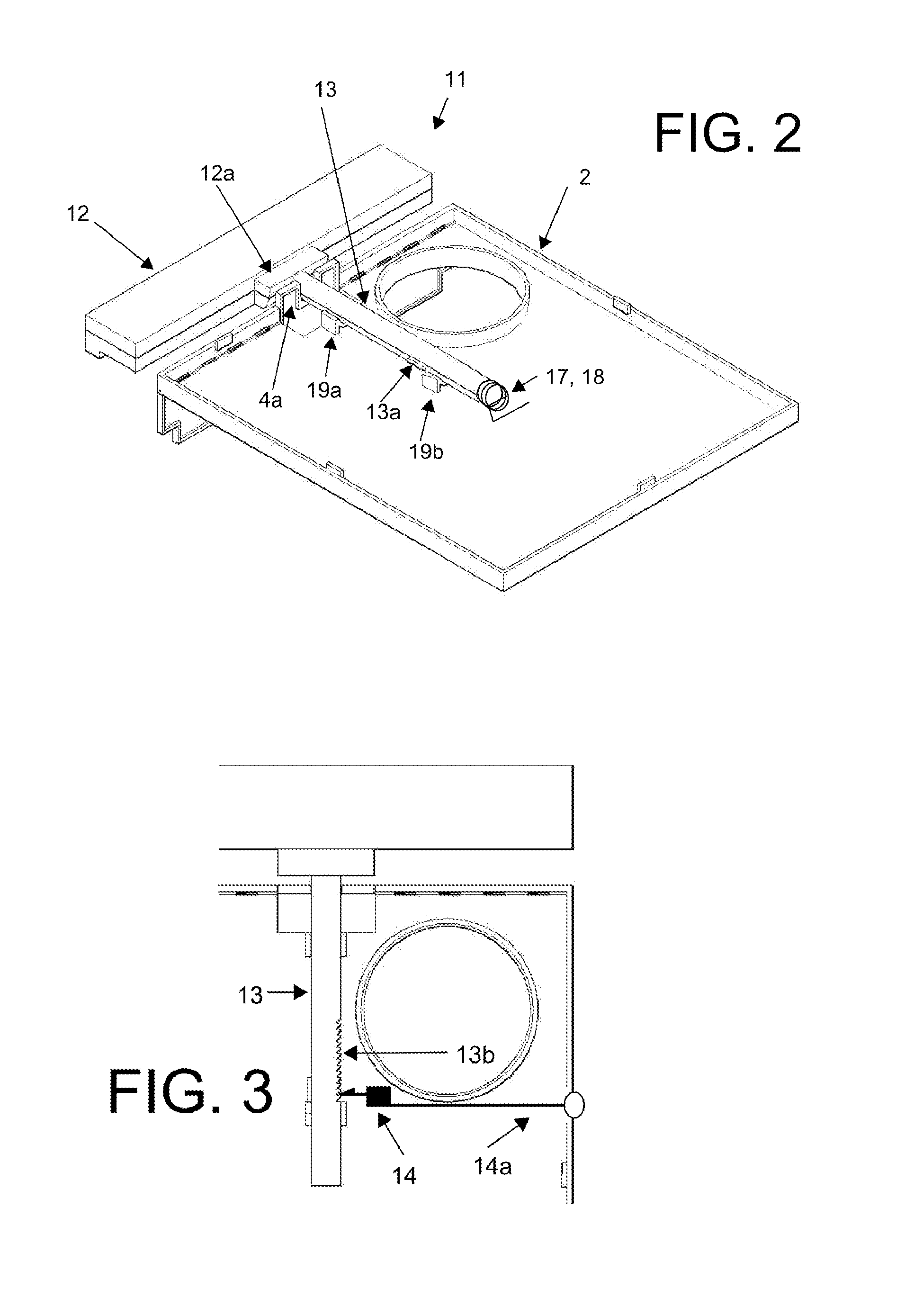
[0031]The fastening means 3 is provided at the distal end of the tabular body and, in this embodiment, comprises a pressing member 11 which is designed in an approximate T shape. As can be seen more clearly in the partially cutaway view in FIG. 2, the pressing member 11 comprises a crosspiece 12 and a slide piece 13, integrally united therewith. The slide piece 13 is received at the interior of the tabular body 2, guided in both translational and rotational m...
second embodiment
[0039]In order to more securely fasten the table 1 to the upright rods A with the fastening means 3, an elastic biasing force may be introduced so as to bias the fastening means 3 against the upright rods A or so as to bias the upright rods A against the distal end of the tabular body 2.
[0040]In a second preferred embodiment of the invention, as shown in FIG. 7, the elastic biasing force is introduced by way of downwardly inclined elastic biasing plates 15 which bias the upright rods A against the distal end of the tabular body 2 and the stiffening wall 4, when the pressing piece 11 is locked in place. These plates may be made of any strong elastic material, such as spring steel or rubber, but in this embodiment they are formed integrally with the crosspiece 12 from a resilient thermoplastic resin. Because the biasing plates 15 press against the upright rods A in a vertically asymmetrical manner, a slight moment is produced in the pressing member 11, and hence in the tabular body 2,...
third embodiment
[0041]In a third embodiment of this invention shown in FIG. 8, the fastening means 3 comprises first and second elongate notches 21, 22, having square-U shapes, which are provided in the vicinity of the distal end of the tabular body 2. In the drawing, the notch 21 opens to the top of the figure and the notch 22 opens to the bottom of the figure. In the notch 21 a first upwardly inclined elastic biasing plate 23 is provided such that the fixed end is united with the bottom of the first elongate notch 21 and the free end is positioned above the fixed end. In the notch 22, a second downwardly inclined elastic biasing plate 24 is provided such that the fixed end is united with the top of the second elongate notch 22 and the free end is positioned below the fixed end.
[0042]By virtue of this configuration, the table 1 can be introduced sideways between two upright rods A so that the top face of the tabular body 2 faces the upright rod A on the left hand side and the bottom face of the ta...
PUM
 Abstract
Description
Claims
Application Information
 - R&D
- Intellectual Property
- Life Sciences
- Materials
- Tech Scout
- Unparalleled Data Quality
- Higher Quality Content
- 60% Fewer Hallucinations
Browse by: Latest US Patents, China's latest patents, Technical Efficacy Thesaurus, Application Domain, Technology Topic, Popular Technical Reports.
© 2025 PatSnap. All rights reserved.Legal|Privacy policy|Modern Slavery Act Transparency Statement|Sitemap|About US| Contact US: help@patsnap.com