
Frame Distortion Control

a frame and control technology, applied in the direction of control using feedback, ways, constructions, etc., can solve the problems of machine frame distortion, very wide equipment,

Active Publication Date: 2016-06-23
WIRTGEN GMBH
View PDF11 Cites 19 Cited by
  • Summary
  • Abstract
  • Description
  • Claims
  • Application Information

AI Technical Summary

Benefits of technology

The patent describes a construction machine apparatus with a frame and laser sensors for detecting the height of the machine frame relative to a reference point. The machine frame has adjustable supports for adjusting its width and length. The laser sensors detect the height of the machine frame at different locations on the frame, and the controller uses these measurements to control the height adjustment of the supports. This allows for precise control of the machine frame's shape as it moves forward. The patent also describes a method for operating the construction machine and a slipform paver with adjustable width and length. The technical effects of the patent include improved control of the machine frame's shape and improved accuracy of the laser sensors.

Problems solved by technology

While controls of the type just described may be perfectly suitable for equipment with very rigid frames such as for example a typical road milling machine, an additional problem is encountered with very wide equipment, such as for example a grade trimming machine or a slipform paving machine.
With these relatively wide frames, and particularly with frames which are extendable in width and / or length, a problem may be encountered with the distortion of the machine frame due to its inherent flexibility and the very heavy loads placed on the frame.

Method used


Image

  • Frame Distortion Control
  • Frame Distortion Control
  • Frame Distortion Control

Examples


Embodiment Construction

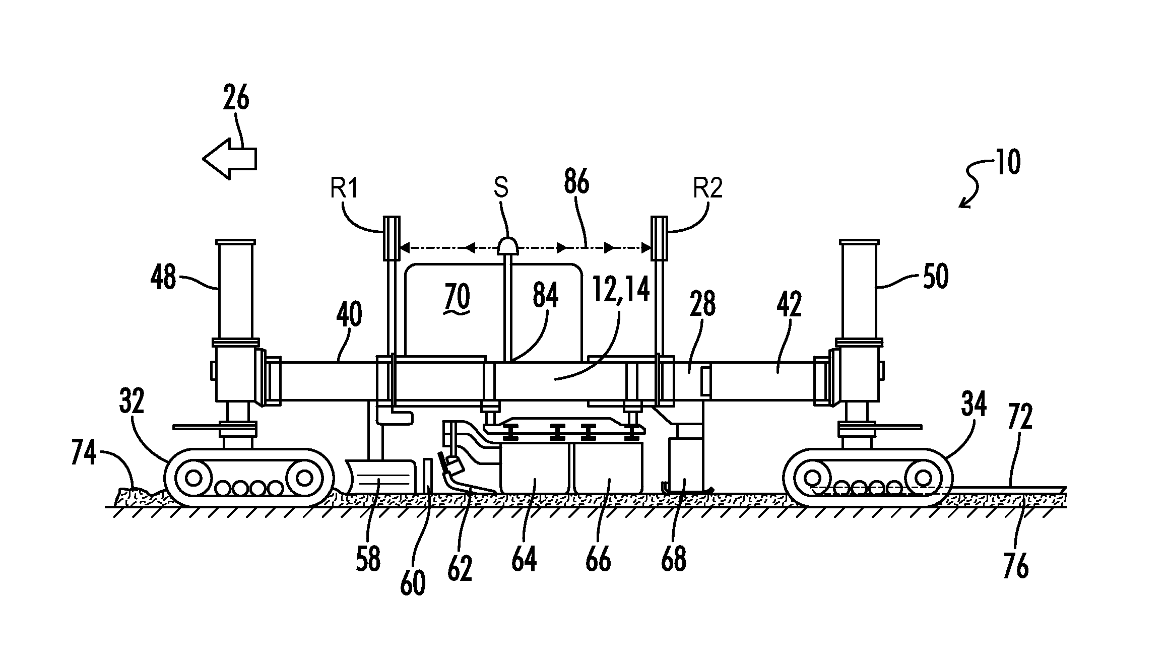
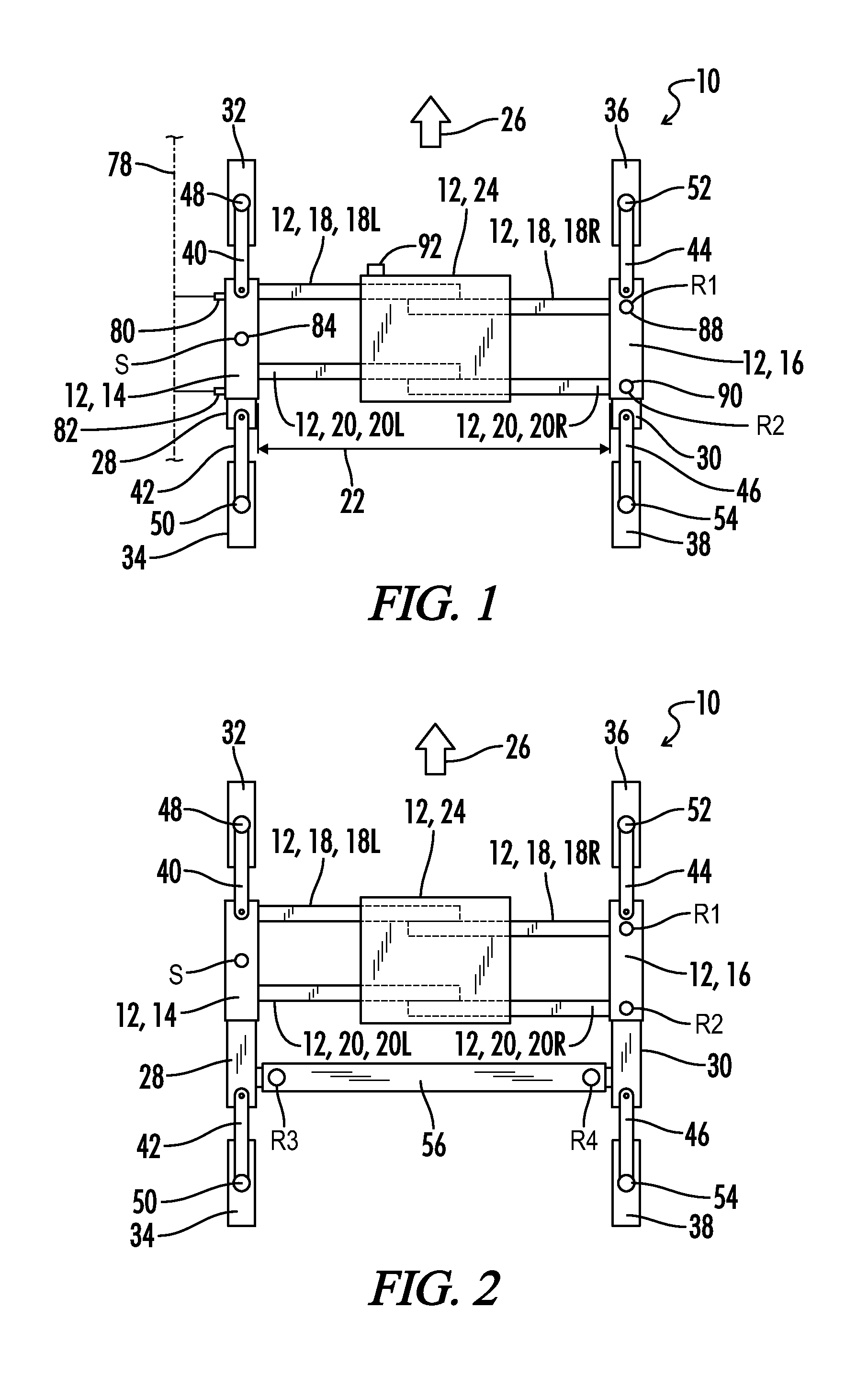
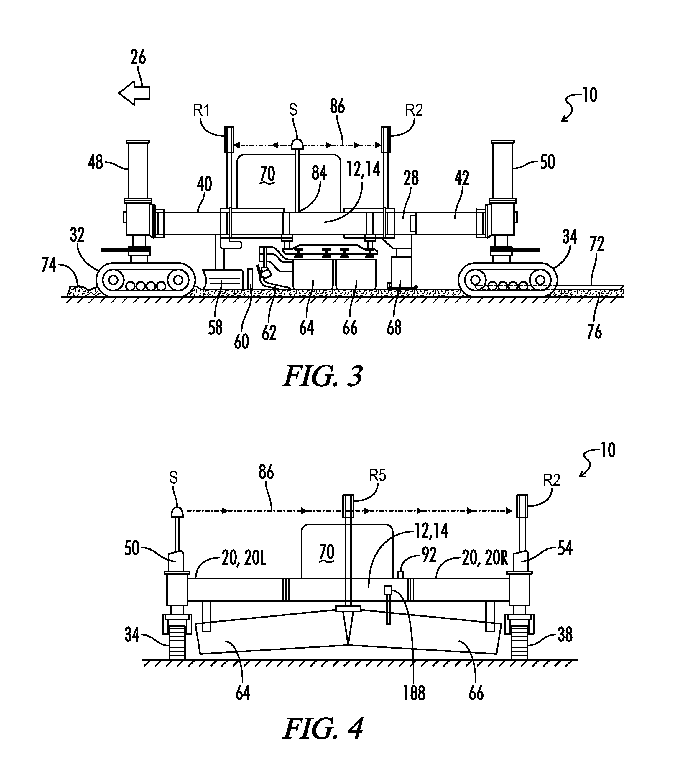
[0038]FIG. 1 schematically illustrates a construction machine apparatus 10, which in the illustrated embodiment is a slipform paving apparatus 10. The apparatus 10 includes a machine frame 12. Machine frame 12 includes a reference side frame member 14 and a control side frame member 16. Front and rear transverse frame members 18 and 20 are connected to the side frame members 14 and 16. In the case illustrated, each of the front and rear transverse frame members 18 and 20 is a telescoping frame member which provides that a width 22 of the frame 12 between the side frame members is adjustable.

[0039]The machine frame 12 includes a center frame module 24. The front transverse frame member 18 comprises left and right front telescoping members 18L and 18R which are attached at their outer ends to their respective side frame members 14 and 16, and which are telescopingly received within the center frame module 24 as indicated by the dashed portions of the telescoping members 18L and 18R wi...


PUM


Abstract

A slipform paving machine includes a laser source for generating a laser reference plane. At least two laser receivers are mounted on the machine and intersect the laser reference plane. Inputs from the laser receivers are utilized to control distortion of the frame of the slipform paver machine.

Description

BACKGROUND OF THE INVENTION[0001]1. Field of the Invention[0002]The present invention relates generally to height control systems for controlling the height of a construction machine, and more particularly, but not by way of limitation, to such systems for use in slipform paving machines.[0003]2. Description of the Prior Art[0004]In all construction machines which are utilized for preparing a ground surface, such as road milling machines, surface stabilizing machines, ground trimmer machines, or in construction machines for forming structures on a ground surface, such as a slipform paving machine, one important factor is the control of the height of the working implements and thus the grade or height of the ground surface being prepared or the structure being formed.[0005]Such construction machines typically take a reference reading from a string line which has been placed on one or both sides of the intended path of the machine, or in some instances a reference is taken from an exi...

Claims


Application Information

Patent Timeline
IPC IPC(8): E01C19/48E01C19/22E01C19/00
CPCE01C19/484E01C19/4853E01C19/22E01C19/006E01C19/00E01C19/48G05D3/12E01C19/42
Inventor FRITZ, MATTHIASDAHM, MARTINLENZ, MARTINBARIMANI, CYRUSHAHN, GUNTER
Owner WIRTGEN GMBH
Learn More