Liquid crystal display device

Active Publication Date: 2016-06-30
JAPAN DISPLAY INC
View PDF3 Cites 1 Cited by
  • Summary
  • Abstract
  • Description
  • Claims
  • Application Information

AI Technical Summary

Benefits of technology

[0009]It is an object of the present invention to achieve a practical use of a liquid crystal display

Problems solved by technology

In some cases, even typical FFS liquid cryst

Method used


Image

  • Liquid crystal display device
  • Liquid crystal display device
  • Liquid crystal display device

Examples


Example

First Embodiment

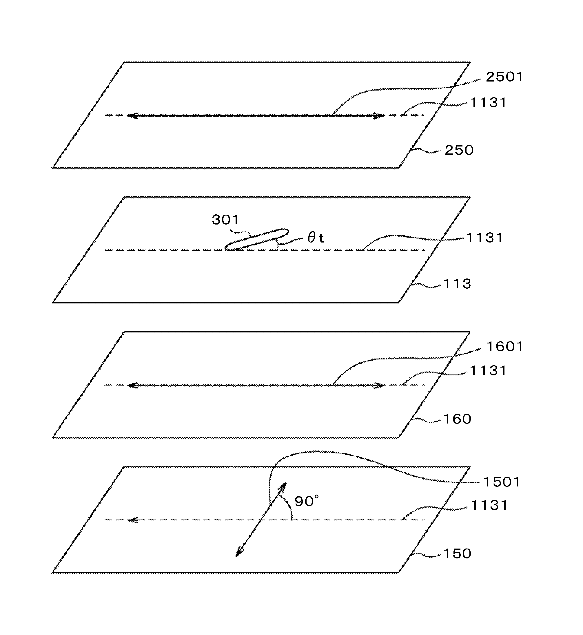
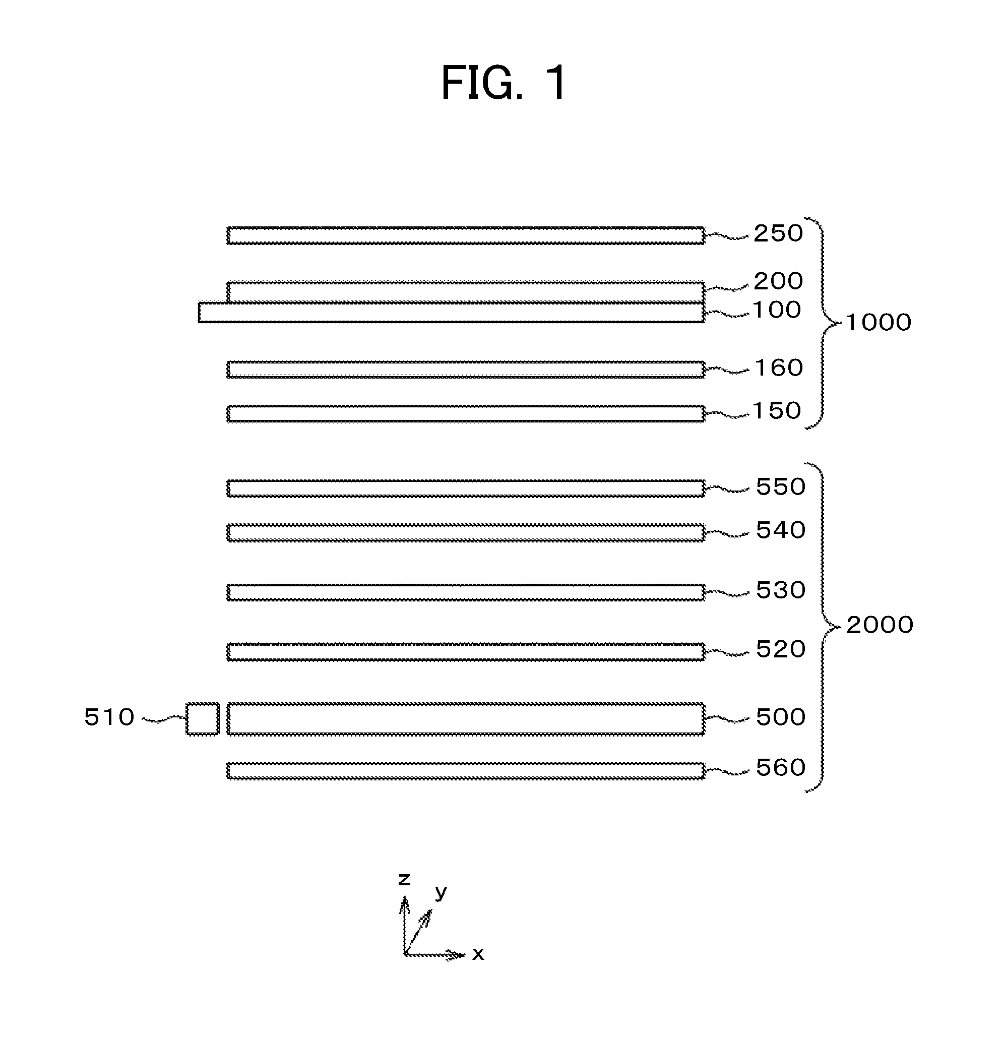
[0039]FIG. 1 is an exploded cross sectional view of a liquid crystal display device. In FIG. 1, to a TFT substrate 100, a counter substrate 200 is attached in the edge area with a sealing material. A liquid crystal is sandwiched between the TFT substrate 100 and the counter substrate 200. A retardation plate 160 is attached on the lower side of the TFT substrate 100. A lower polarizer 150 is attached on the lower side of the retardation plate 160. An upper polarizer 250 is attached on the upper side of the counter substrate 200. Light from a backlight 2000 is converted into linear polarized light at the lower polarizer 150. The polarization axis of the polarized light is changed at the retardation plate 160 to improve the viewing angle characteristics. The TFT substrate 100, the counter substrate 200, the retardation plate 160, the lower polarizer 150, and the upper polarizer 250 are referred to as a liquid crystal display panel 1000. In the following embodiment, the...


PUM


Abstract

In an FFS liquid crystal display device, viewing angle characteristics are further improved. In an FFS liquid crystal display device, the alignment axis of a first alignment film of a first substrate and the alignment axis of a second alignment film of a second substrate are directed in the same direction. At least two of an upper polarizer, a lower polarizer, or a retardation plate 160 satisfy conditions below. (1) The absorption axis of the upper polarizer forms an angle of one to 45 degrees inclusive with the alignment axis. (2) The absorption axis of the lower polarizer forms an angle of 91 to 135 degrees inclusive or forms an angle of 45 to 89 degrees inclusive with the alignment axis. (3) The extension axis of the retardation plate 160 forms an angle of one to 45 degrees inclusive with the alignment axis.

Description

CLAIM OF PRIORITY[0001]The present application claims priority from Japanese Patent Application JP 2014-267007 filed on Dec. 29, 2014, the content of which is hereby incorporated by reference into this application.BACKGROUND OF THE INVENTION[0002](1) Field of the Invention[0003]The present invention relates to a display device, and more specifically to a liquid crystal display device that improves viewing angle characteristics.[0004](2) Description of the Related Art[0005]A liquid crystal display device includes a TFT substrate and a counter substrate. The TFT substrate is formed with a pixel having a pixel electrode, a thin film transistor (TFT), and other elements formed in a matrix configuration. The counter substrate is disposed opposite to the TFT substrate. A liquid crystal is sandwiched between the TFT substrate and the counter substrate. The light transmittance of liquid crystal molecules is controlled for each pixel to form images.[0006]The liquid crystal has a problem of v...

Claims


Application Information

Patent Timeline
IPC IPC(8): G02F1/1335G02F1/1343G02F1/13363G02F1/1337
CPCG02F1/133528G02F1/1337G02F2001/133531G02F1/13363G02F1/134309G02F2413/08G02F1/134372
Inventor NISHIKAWA, MASAKIOOSHIMA, TETSUYA
Owner JAPAN DISPLAY INC
Why Eureka
Try Eureka