Substrate with recess portion for microlens, microlens substrate, transmissive screen, rear type projector, and method of manufacturing substrate with recess portion for microlens

Inactive Publication Date: 2005-06-16
SEIKO EPSON CORP
View PDF19 Cites 138 Cited by
  • Summary
  • Abstract
  • Description
  • Claims
  • Application Information

AI Technical Summary

Benefits of technology

[0046] Thereby, the substrate with the recess portions for the microlenses, which allows manufacturing of the microlens substrate having an excellent view angle characteristi

Problems solved by technology

As a result, in the rear type projector using such a microlens s

Method used


Image

  • Substrate with recess portion for microlens, microlens substrate, transmissive screen, rear type projector, and method of manufacturing substrate with recess portion for microlens
  • Substrate with recess portion for microlens, microlens substrate, transmissive screen, rear type projector, and method of manufacturing substrate with recess portion for microlens
  • Substrate with recess portion for microlens, microlens substrate, transmissive screen, rear type projector, and method of manufacturing substrate with recess portion for microlens

Examples


embodiments

Embodiment 1

[0192] The substrate with the recess portions for the microlenses comprising the recess portions for microlenses is manufactured, and the microlens substrate is manufactured using the substrate with the recess portions for the microlenses, as follows.

[0193] First, as the substrate, a non-alkali glass substrate with 1.2 m×0.7 m square and a thickness of 0.7 mm is prepared.

[0194] This non-alkali glass substrate is soaked in cleaning fluid (monohydric difuluoride ammonium solution of 4 wt %) at room temperature, to carry out cleaning, and the surface thereof is cleaned.

[0195] -1A- Next, on this non-alkali glass substrate, a Cr / Cr-oxide film (mask) with a thickness of 0.15 μm is formed by a sputtering method.

[0196] -2A- Next, a plurality of first initial holes are formed within the area of the center portion with 113 cm×65 cm of the mask by carrying out laser processing to the mask.

[0197] In addition, the laser processing is carried out using YAG laser with the energy ...

embodiment 2

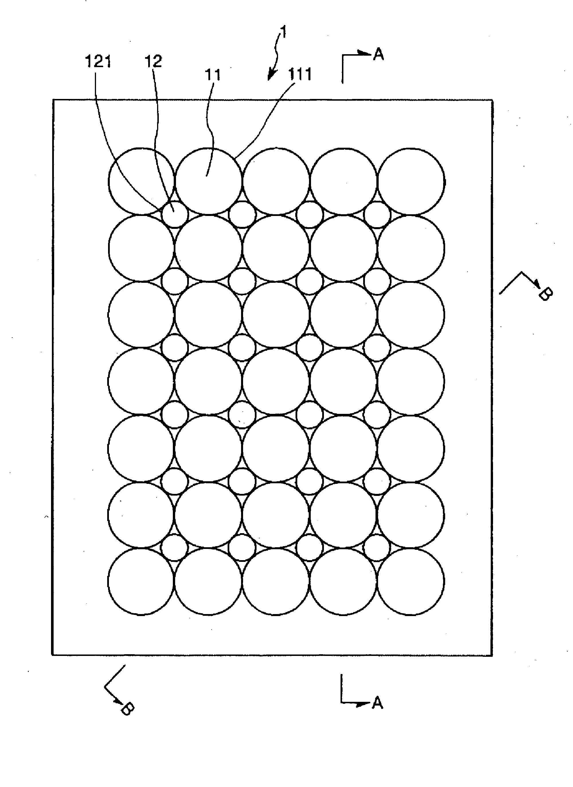
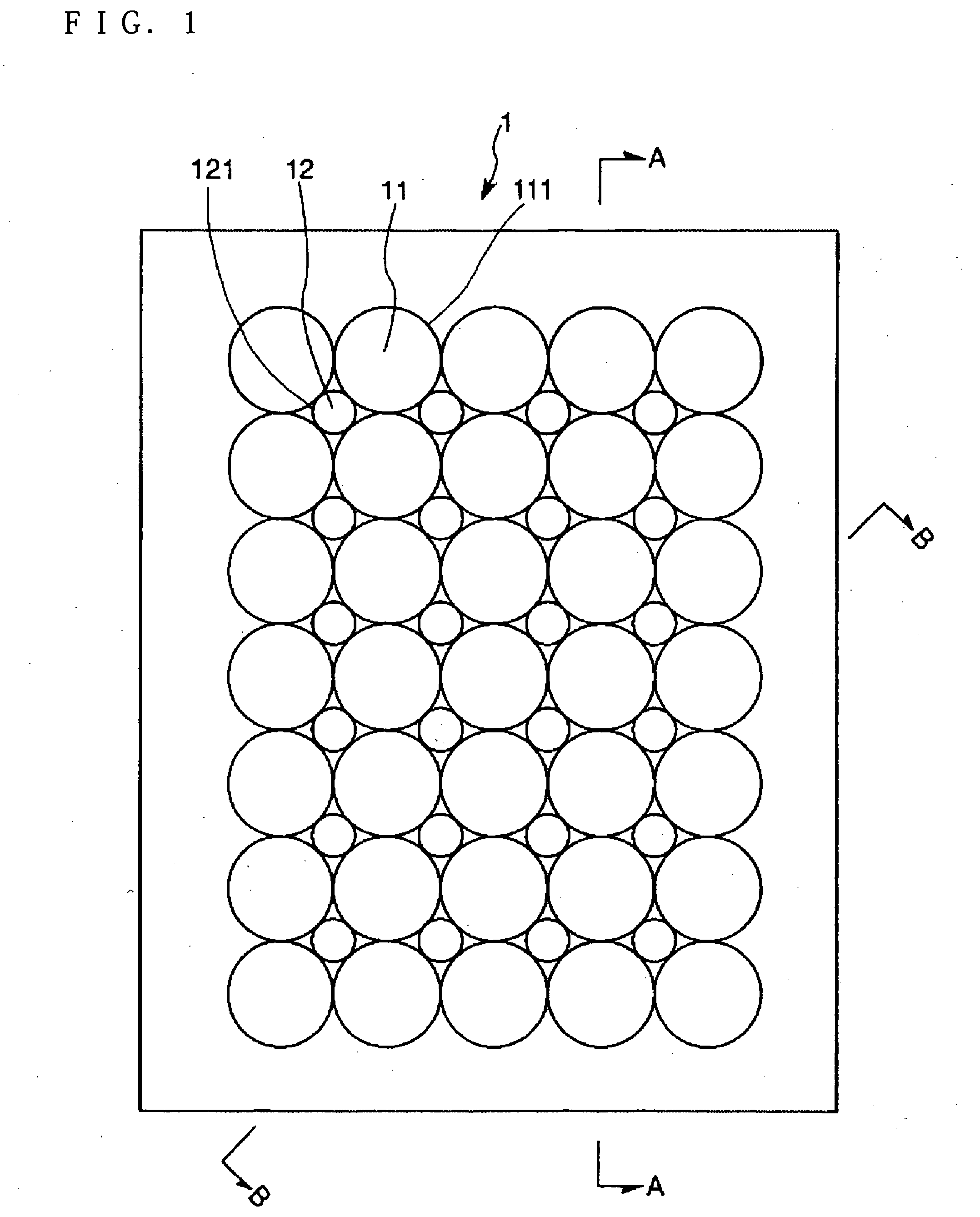
[0211] The same substrate with the recess portions for the microlenses as the above-described embodiment 1 is obtained by the same method as embodiment 1, except that the position of a plurality of first recess portions are made in a staggered-shape, that the size of the second recess portions is made smaller than the above-described embodiment 1, and that the third recess portions are not formed.

[0212] The microlens substrate is obtained by the same method as embodiment 1 using this substrate with the recess portions for the microlenses. Thereby, as shown in FIG. 10B, except that the position of a plurality of first microlenses are made staggered-shaped, that the size of the second microlenses is made smaller than the above-described embodiment 1, and that the third microlenses are not formed, the same microlens substrate as the above-described embodiment 1.

[0213] The obtained diameter of the second microlenses is 20 μm (=curvature radius). Moreover, the height of the second micr...

embodiment 3

[0214] Except that the periphery shape of the first recess portions is made a straw bag shape, and that the third recess portions are not formed, the same substrate with the recess portions for the microlenses as the above-described embodiment 1 is obtained by the same method as embodiment 1. In this case, the first initial holes are made long holes extending by 50 μm upwards and downwards (in opposite directions).

[0215] The microlens substrate is obtained by the same method as embodiment 1 using this substrate with the recess portions for the microlenses. Thereby, as shown in FIG. 11A, except that the shape of the first microlenses is a straw bag shape, and that the third microlenses are not formed, the same microlens substrate as the above-described embodiment 1, is obtained.

[0216] The length in the long axis direction of the formed first microlenses is 150 μm, and the length in the short axis direction of the first microlenses is 110 μm.


PUM


Abstract

A microlens substrate is provided having a plurality of first microlenses and a plurality of second microlenses which are located between the plurality of first microlenses. The second microlenses are smaller than the first microlenses.

Description

RELATED APPLICATIONS [0001] This application claims priority to Japanese Patent Application No. 2003-418654 filed Dec. 16, 2003 which is hereby expressly incorporated by reference herein in its entirety. BACKGROUND [0002] 1. Field of the Invention [0003] The present invention relates to a substrate with recess portions for microlenses, a microlens substrate, a transmissive screen, a rear type projector, and a method of manufacturing a substrate with recess portions for microlenses. [0004] 2. Description of the Related Art [0005] A display device which projects pictures on a screen is known. As for such display device, a rear type projector applied to a home theater monitor, a big-screen TV, and the like is known. [0006] One known rear type projector includes a lens substrate (microlens substrate) having microlenses. In such a rear type projector, there is an advantage in that the view angle characteristic is improved both in the horizontal direction and in the vertical direction of ...

Claims


Application Information

Patent Timeline
IPC IPC(8): B29D11/00G02B3/00G03B21/10G03B21/62
CPCG02B3/0056G02B3/0031B29D11/00365G02B1/041G03B21/10
Inventor SHIMIZU, NOBUO
Owner SEIKO EPSON CORP
Why Eureka
Try Eureka