Hydraulic actuators

Active Publication Date: 2016-07-21
BAE SYSTEMS PLC
View PDF1 Cites 0 Cited by
  • Summary
  • Abstract
  • Description
  • Claims
  • Application Information

AI Technical Summary

Benefits of technology

[0006]The present inventor has realised that it is desirable to use plural self-contained or closed hydraulic systems on a vehicle, in particular an aircraft, to achieve for example an advantage that each can be serviced or replaced independently of the others, thereby avoiding for example the need to drain a shared hydraulic system. The present inventor has realised that such an arran

Problems solved by technology

The present inventor has realised that such an arrangement tends to have a disadvantage that high gearing or other measures

Method used


Image

  • Hydraulic actuators
  • Hydraulic actuators
  • Hydraulic actuators

Examples


Embodiment Construction

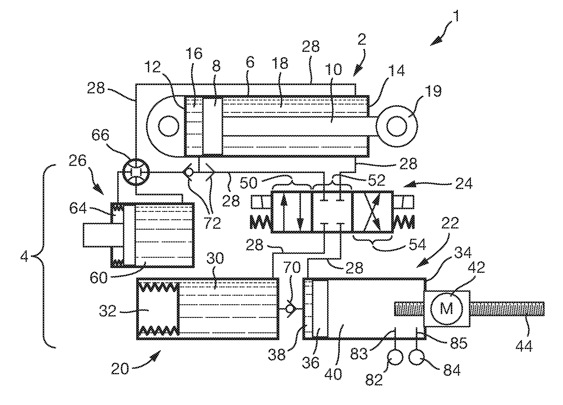
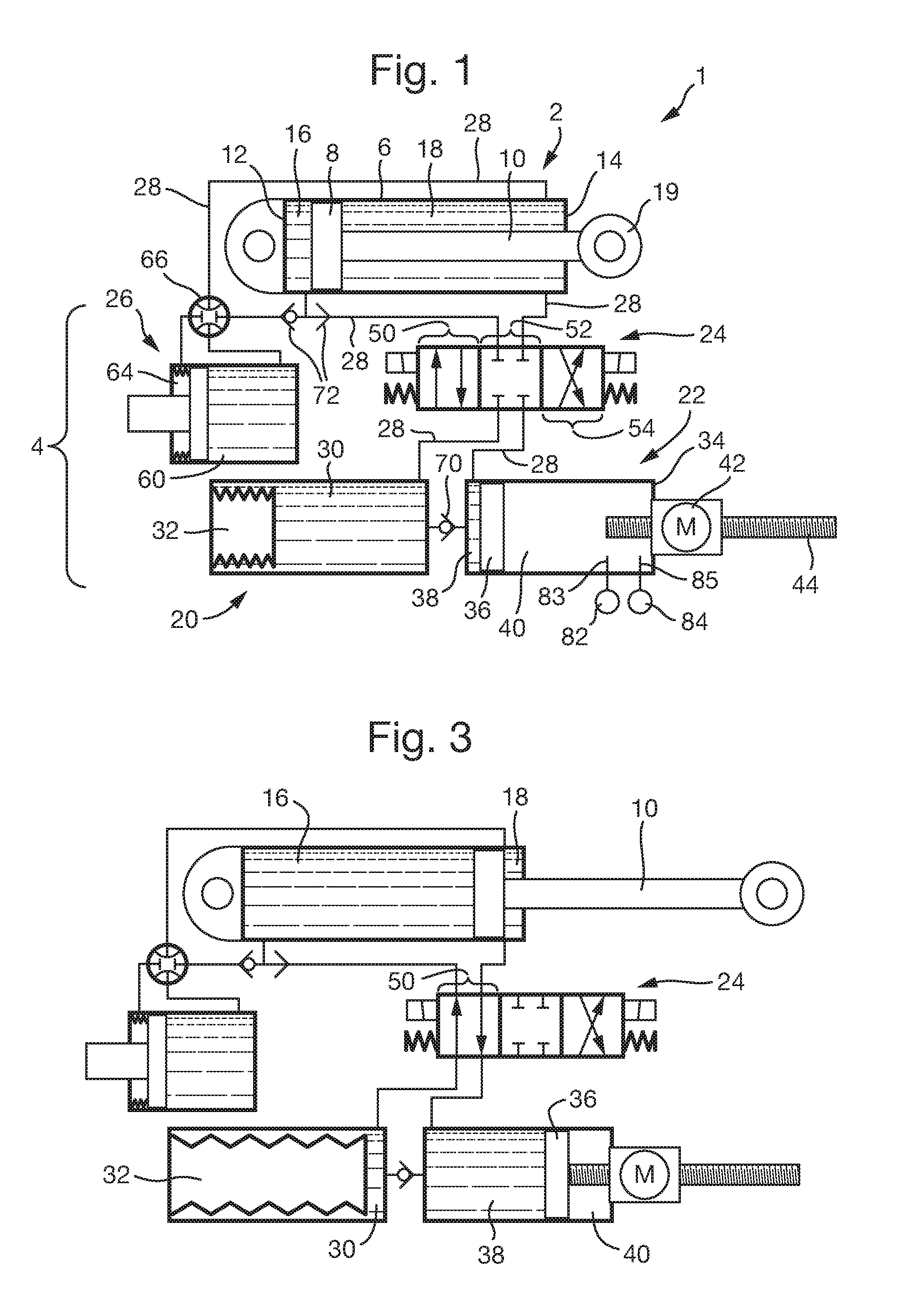
[0049]FIG. 1 is a schematic illustration (not to scale) of a first embodiment of a hydraulic actuator system 1.

[0050]In this embodiment the hydraulic actuator system 1 comprises a linear hydraulic actuator 2 that is hydraulically coupled to a hydraulic charging and driving system 4 adapted to hydraulically charge the linear hydraulic actuator 2.

[0051]In this embodiment the linear hydraulic actuator 2 comprises a cylinder barrel 6, a piston (which may also be termed an actuator valve) 8, and a piston rod 10 attached to the piston 8. The piston is arranged to be able to move back and forth along the cylinder barrel 6. The cylinder barrel 6 is closed at one end by a cylinder base (which may also be termed cap) 12. The cylinder barrel 6 is closed at its other end by a cylinder head 14 where the piston rod 10 comes out of the cylinder barrel 6. The piston 8 divides the inside of the cylinder barrel 6 into two chambers, namely a bottom chamber 16 at the cylinder base 12 side of the piston...


PUM


Abstract

A hydraulic charging and driving system (4), aircraft employing the same, and corresponding methods, for extending and retracting a hydraulic actuator (2), comprising: a motor assembly (22); and an accumulator assembly (20), the motor assembly (22) and the accumulator assembly (20) being hydraulically coupled to each other; wherein the motor assembly (22) is arranged to recharge the accumulator assembly (20) with hydraulic fluid at a relatively slow rate that is slower than the rate at which the accumulator assembly (20) is arranged to discharge when actuating the hydraulic actuator (2). The system may further comprise a selector valve (24). The accumulator assembly (20) may comprise an accumulator chamber (30), and a compression means (32) provided within the accumulator chamber (30). The motor assembly (22) may comprise a motor (42) arranged to vary a volume of a hydraulic charging chamber (38) of the motor assembly (22).

Description

RELATED APPLICATIONS[0001]This application is a U.S. National Application which claims priority to GB Patent Application 1500553.1 filed Jan. 14, 2015. This application is herein incorporated by reference in its entirety for all purposes.FIELD OF THE INVENTION[0002]The present invention relates to hydraulic actuators and hydraulic actuator systems. The present invention relates in particular to, but is not limited to, hydraulic actuators and hydraulic actuator systems for aircraft.BACKGROUND[0003]The use of hydraulic actuators, for example in aircraft, is well established. For example, they are used for flight control applications such as moving control flaps, for landing gear extension and retraction, and so on.[0004]Conventionally, a plurality of actuators are coupled to a common hydraulic circuit that comprises a reservoir and a pump. An advantage of hydraulic actuators is the ability to provide a relatively high power density.[0005]A disadvantage of the above described arrangeme...

Claims


Application Information

Patent Timeline
IPC IPC(8): F15B1/027F15B11/08F15B1/08
CPCF15B1/027F15B2201/00F15B11/08F15B1/08B64C13/40F15B1/033F15B7/00F15B2211/212F15B2211/625F15B2211/7053F15B2211/864F15B2211/8752
Inventor HARE, COLIN
Owner BAE SYSTEMS PLC
Why Eureka
Try Eureka