
Steam box control method and steam box

A control method and technology of a steam box, which are applied in the steam generation method, timing control ignition mechanism, steam generation and other directions, can solve the problems of low heating efficiency, etc., and achieve the effect of improving the effect, shortening the time, and short the heat conduction distance.

Pending Publication Date: 2021-12-03
NINGBO FOTILE KITCHEN WARE CO LTD
View PDF0 Cites 0 Cited by
  • Summary
  • Abstract
  • Description
  • Claims
  • Application Information

AI Technical Summary

Problems solved by technology

[0004] The technical problem to be solved by the present invention is to provide a steamer control method and a

Method used


Image

  • Steam box control method and steam box
  • Steam box control method and steam box
  • Steam box control method and steam box

Examples


Embodiment 1

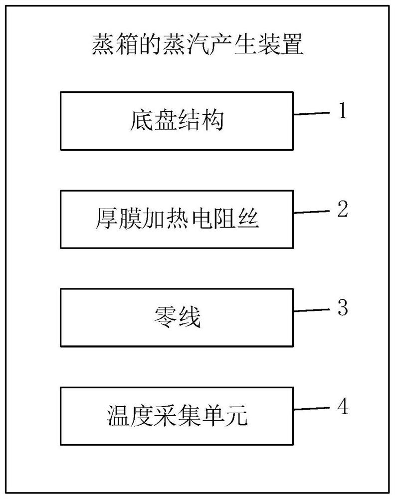
[0051] Such as figure 1 As shown, this embodiment provides a steam generating device for a steam box. The steam generating device includes: a chassis structure 1, and at least one group of thick film heating resistance wires 2 arranged on the chassis structure 1, adjacent thick film heating resistance wires are coiled independently or in parallel, and each group of thick film heating resistance wires The wires are all connected to the same zero line 3; the temperature acquisition unit 4 is in contact with each group of thick film heating resistance wires, and the temperature acquisition unit is used to collect the temperature data of the thick film heating resistance wires.

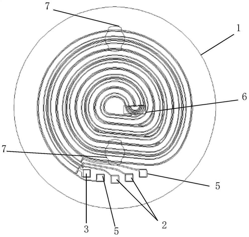
[0052] Such as figure 2 As shown, in an optional embodiment, the steam generating device includes two sets of thick-film heating resistance wires 2; two sets of thick-film heating resistance wires 2 are coiled and arranged on the chassis structure 1 in parallel.

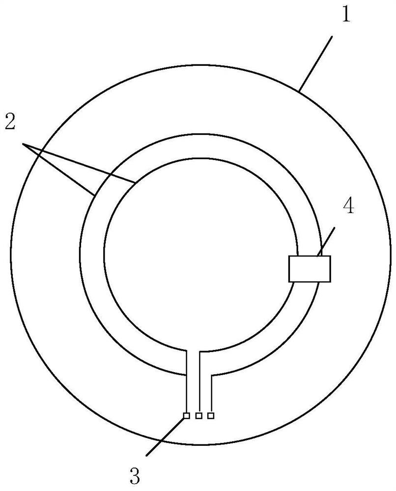
[0053] Such as image 3 As shown, in ...

Embodiment 2

[0090] Such as Figure 7 As shown, this embodiment provides a steam box, including a box body 8 and the steam generating device 9 in embodiment 1 or embodiment 2; the steam control device 9 is arranged inside the box body.

[0091] The steam box can also include other components such as a water tank, a water pump and a water pipe; the water tank and the water pump are arranged outside the casing, the water tank and the water pump are connected to the steam generating device through the water pipe, and the water pump is electrically connected to the controller of the steam generating device; the controller is used for A steam generating unit that controls the water pump to draw water from the tank to the steam generating unit.

[0092] In an optional embodiment, the steam box further includes a display, which is arranged outside the box and is electrically connected to the controller. The controller can send the display information to the display, so that the display can displ...


PUM

PropertyMeasurementUnit
Thicknessaaaaaaaaaa

Abstract

The invention discloses a steam box control method and a steam box. The steam box comprises a steam generating device, which comprises a base plate structure and at least one group of thick film heating resistance wires arranged on the base plate structure,wherein the adjacent thick film heating resistance wires are independently coiled or parallelly coiled; and a temperature collecting unit is in contact connection with each group of thick film heating resistance wires. The steam box control method comprises the following steps: controlling a thick film heating resistance wires to heat at first power; detecting the actual temperature value of the steam box; when the actual temperature value of the steam box reaches the first preset temperature, controlling the thick film heating resistance wires to stop heating; and when the actual temperature value in the steam box cavity is reduced and is lower than a second preset temperature, controlling the thick film heating resistance wires to heat for a preset time length at a second power. According to the steam generation device, the steam generation time of the steam box is greatly shortened,and the heat efficiency of the steam box is higher; and the cooking time is effectively shortened through the control mode of the steam box, the food taste is improved, and the use experience of a user is improved.

Description

technical field [0001] The invention relates to the technical field of smart home appliances, in particular to a steam box control method and the steam box. Background technique [0002] The steam box can quickly generate steam, so that the food in the steam box is quickly surrounded by saturated steam, which speeds up the cooking time and improves the freshness of the food, which is becoming a trend. The steamer cooks food by heating water to generate water vapor, so the heating device is an essential part of the steamer. At present, the existing technical scheme of the steam box to generate steam and the control method is to use an aluminum heating tube, and use a thermistor to detect the temperature to detect whether there is water in the heating plate, and a simple control method based on this heating device. [0003] The existing steam box heating technology scheme is affected by the 15W / cm of aluminum heating tube 2 Due to the limitation of power density, under the e...

Claims


Application Information

Patent Timeline
IPC IPC(8): A47J36/00A47J27/04F22B1/28
CPCA47J36/32A47J27/04F22B1/28A47J2027/043
Inventor 王玉鹏王伟方献良
Owner NINGBO FOTILE KITCHEN WARE CO LTD
Learn More