Rotating electrical machine and aircraft having said machine

US20210044188A1Active Publication Date: 2021-02-11ROLLS ROYCE DEUT LTD & CO KG

Image

  • Rotating electrical machine and aircraft having said machine
  • Rotating electrical machine and aircraft having said machine
  • Rotating electrical machine and aircraft having said machine

Examples


Embodiment Construction

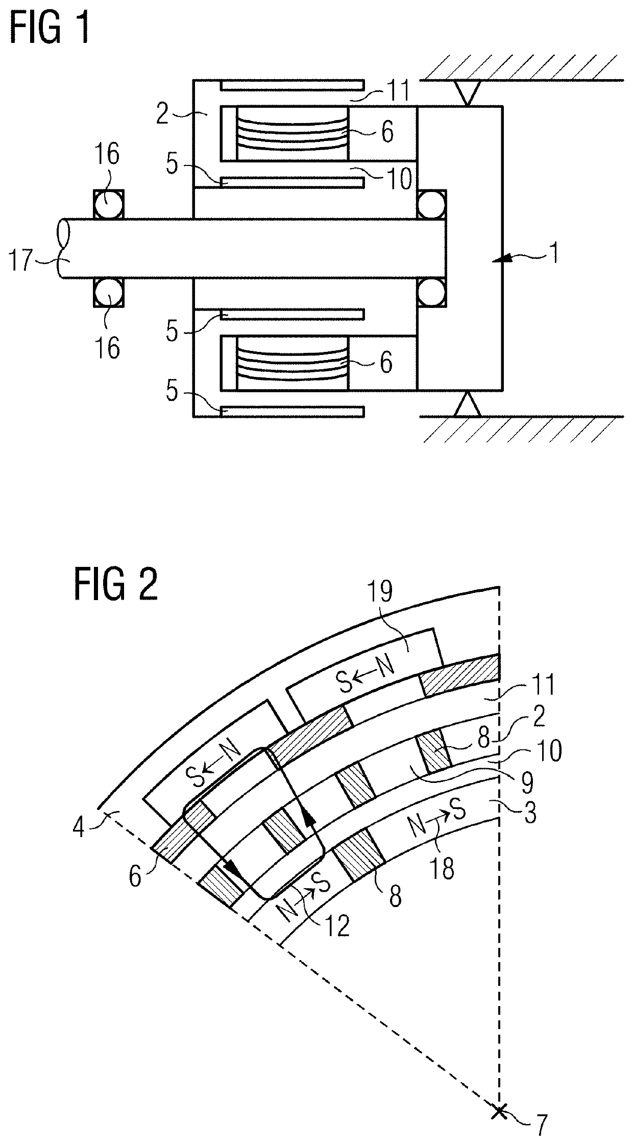
[0040]FIG. 2 shows a cross section through a part of a rotating electric machine, where an axis of rotation 7 of a rotor 2 projects out of the plane of the image. The rotor 2 is of tubular form and has a ferromagnetic material 9 and a non-magnetic material 8 in alternation in a circumferential direction. In other words, the rotor 2 forms a type of toothed ring, where the ferromagnetic material 9 forms the teeth. The rotor 2 lies concentrically between a ring-shaped inner first stator 3 (e.g., a first stator 3) and a ring-shaped second stator 4 (e.g., a second stator 4).

[0041]The first stator 3 has first magnets 18 that are arranged spaced apart from one another in a circumferential direction, where S and N poles of adjacent first magnets 18 face toward one another. The first magnets 18 may be formed as Halbach arrays.

[0042]The second stator 4 has second magnets 19 that are arranged spaced apart from one another in a circumferential direction, where S and N poles of adjacent second m...


PUM


Abstract

The invention relates to a rotating electrical flux-switching machine, comprising a rotatable tubular rotor (2), an inner first stator (3), and an outer second stator (4) that is concentric and spaced apart relative to the first stator (3), wherein the rotor (2) is arranged concentrically relative to the first and second stator (3, 4) and is arranged between the first and the second stator (3, 4) in such a way that a first air gap (10) is formed between the first stator (3) and the rotor (2), and a second air gap (11) is formed between the second stator (4) and the rotor (2). The invention also relates to an aircraft comprising a rotating electrical machine of this type.

Description

[0001]This application is the National Stage of International Application No. PCT / EP2019 / 051579, filed Jan. 23, 2019, which claims the benefit of German Patent Application No. 10 2018 201 610.0, filed Feb. 2, 2018. The entire contents of these documents are hereby incorporated herein by reference.FIELD[0002]The present embodiments relate to a rotating electric machine and an aircraft having a rotating electric machine.BACKGROUND[0003]For many technical applications, rotating electric machines with a high power-to-weight ratio (kW / kg) have a major advantage. Some applications could be made possible for the first time if rotating electric machines could be constructed with a high power-to-weight ratio. One example is the electrification of air travel using generators or electric motors. In this case, a power-to-weight ratio of at least 10 kW / kg is to be provided (e.g., Halbach arrays).[0004]Configurations with a double rotor may be electromagnetically advantageous because such configu...

Claims


Application Information

Patent Timeline
11 Feb 2021
Publication
US20210044188A1
IPC
H02K16/04; B64D27/24
CPC
H02K16/04; B64D27/24; H02K21/38; H02K21/40; H02K21/44; Y02E10/72
Inventors
FILIPENKO, MYKHAYLO