
Eureka
For R&D, Eureka makes reading and utilizing patents & technical documents easy.
Eureka AIR
Designed for self-driven R&D workflows. Generate viable solutions, solve complex R&D challenges, empower your innovation with AI.

Eureka Materials
Designed for material experts only. Revolutionize your material R&D, from search, analyze, to developing new materials.

TechResearch
Generate reliable direction feasibility study reports for your R&D in just a few steps.

TechSeek
Discover and master advanced knowledge NOW. Basics, ideas, possibilities, all at once.

TechMind
As an expert in R&D Theories, TechMind can generates customized viable solutions instantly.

TechRisk
Analyze your overall solution with one click, know your potential R&D risks in advance.

TechMonitor
Get weekly tech updates, stay abreast of the latest tech innovations and key insights.
Scanning optical apparatus
- Summary
- Abstract
- Description
- Claims
- Application Information
AI Technical Summary
Benefits of technology
Problems solved by technology
Method used
Image

Examples
first embodiment
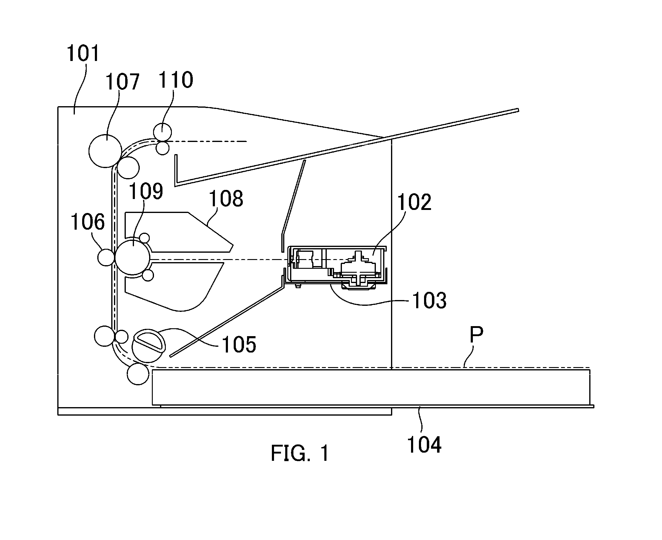
[0038]FIG. 1 is a schematic drawing of an image forming apparatus in which a scanning optical apparatus according to a first embodiment is installed.
[0039]The image forming apparatus 101 includes a scanning optical apparatus 102, an optical bench 103, a paper supply unit 104, a paper supply roller 105, a transfer roller 106, a fixing unit 107 and a process cartridge 108. The scanning optical apparatus 102 forms an electrostatic latent image on a photosensitive drum 109 (image bearing member) of the process cartridge 108, by irradiating (emitting) a laser onto a scanned surface of the photosensitive drum 109. The optical bench 103 is one portion of a housing in the image forming apparatus 101, and the scanning optical apparatus 102 is disposed on the optical bench 103.
[0040]Furthermore, a recording medium P (recording material) on which images are to be formed is stacked in the paper supply unit 104. The paper supply roller 105 supplies the recording medium P stacked in the paper sup...
second embodiment
[0062]Below, a second embodiment of the present invention is now described. In the second embodiment, the shape of the fitting portion in the deflector and the fit receiving portion in the optical box are different to the first embodiment. In the second embodiment, the portions which have the same functions as the first embodiment are labelled with the same reference numerals and description thereof is omitted here. FIG. 8 is a schematic drawing for describing a positioning portion for a deflector in the optical box according to the second embodiment. Furthermore, FIG. 9A and FIG. 9B are cross-sectional diagrams showing a state where the deflector is installed in an optical box in the second embodiment. In FIG. 8, the cross-sectional portions are marked by hatching.
[0063]It is possible to install either one of a deflector 300 (third deflector) which has a shaft 301 (fitting portion) and a deflector 400 (fourth deflector) which has a bearing 401 (fitting portion) in the optical box 2...
PUM
 Abstract
Description
Claims
Application Information
 - R&D Engineer
- R&D Manager
- IP Professional
- Industry Leading Data Capabilities
- Powerful AI technology
- Patent DNA Extraction
Browse by: Latest US Patents, China's latest patents, Technical Efficacy Thesaurus, Application Domain, Technology Topic, Popular Technical Reports.
© 2024 PatSnap. All rights reserved.Legal|Privacy policy|Modern Slavery Act Transparency Statement|Sitemap|About US| Contact US: help@patsnap.com