
Injection molding system with additional injection device

Active Publication Date: 2016-08-25
FANUC LTD
View PDF2 Cites 5 Cited by
  • Summary
  • Abstract
  • Description
  • Claims
  • Application Information

AI Technical Summary

Benefits of technology

This patent is about an injection molding system that makes it easier to arrange wires between devices without compromising maintenance. The system also allows for the interruption of power when a movable door is opened, and can easily notify operators of the state of the position confirmation means for the additional injection device movable door and the injection molding machine movable door. Overall, this invention simplifies the wire arrangement without sacrificing maintainability.

Problems solved by technology

When the movable doors are open, however, movable parts of the injection molding machine are accessible, so that power in the injection molding machine is interrupted for the safety of operators.
If state signals from all the position confirmation switches on the movable doors and those from position confirmation switches on other movable doors are reciprocally input and output between the injection molding machine 1 and the additional injection device 2, therefore, the number of signals increases, possibly wire arrangement is complicated.
If any of the position confirmation switches is out of order, therefore, detection of the disabled switch takes time, possibly decreasing maintainability.

Method used


Image

  • Injection molding system with additional injection device
  • Injection molding system with additional injection device
  • Injection molding system with additional injection device

Examples


Embodiment Construction

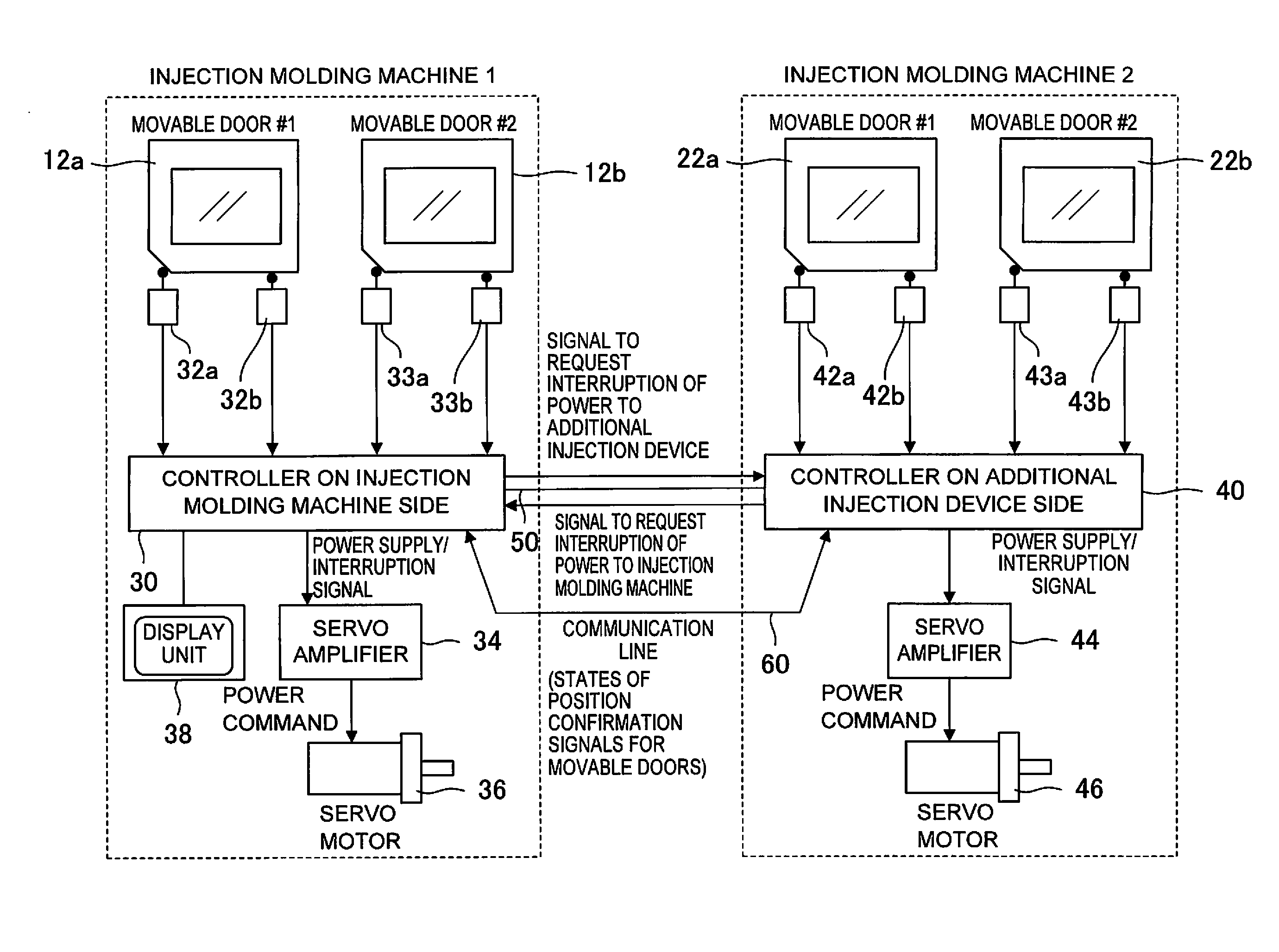
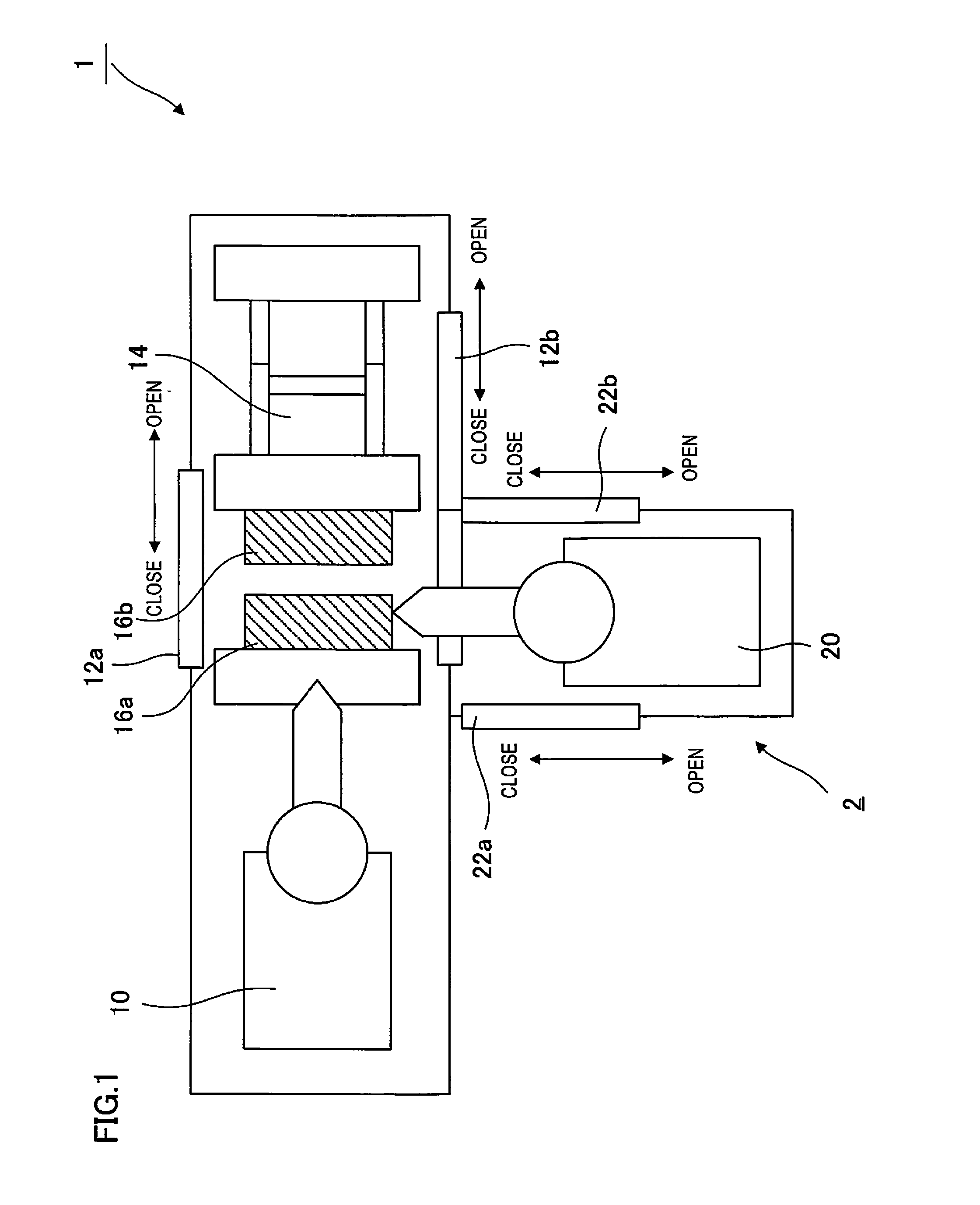
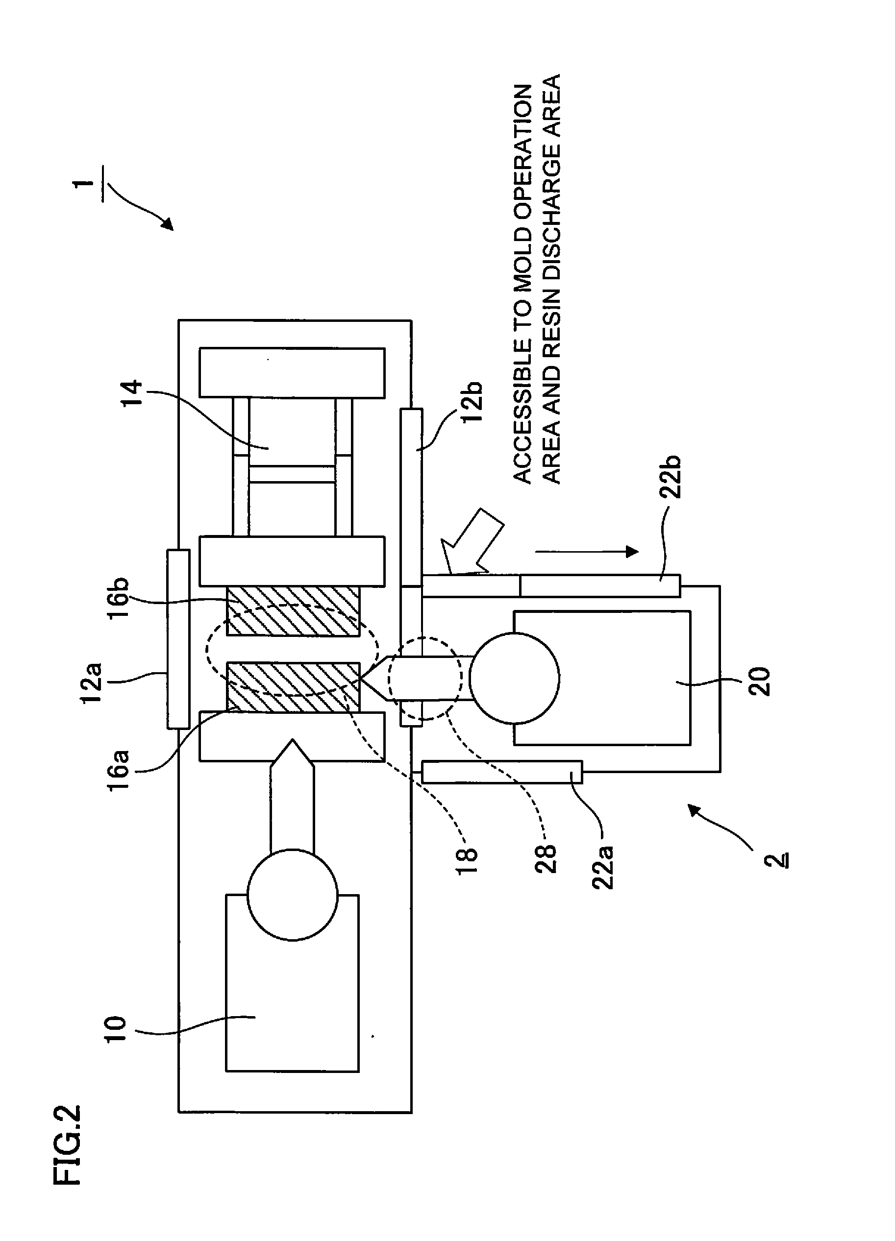
[0030]An embodiment of the present invention will now be described with reference to the accompanying drawings. FIG. 1 and FIG. 2 are top views of the injection molding machine 1 for multi-color, multi-component molding. FIG. 1 is a view showing a state in which the movable doors 12 on the side of the injection molding machine 1 and the movable doors 22 on the side of the additional injection device 2 are all closed. FIG. 2 is a view showing an open state of the movable door 22b on the side of the additional injection device 2. In the state of FIG. 2, an operator can access not only the resin discharge area 28 on the side of the additional injection device 2, but the mold operation area 18 on the side of the injection molding machine 1. As described above, therefore, it is necessary to interrupt the power in the injection mechanism section 10 and the mold clamping mechanism section 14 of the injection molding machine 1, as well as the power in the additional injection device 2, lest...


PUM


Abstract

An injection molding machine and an additional injection device are provided such that a power interruption signal is output to a controller of the injection molding machine or the additional injection device on the destination when it is detected that a movable door is opened and a state of position confirmation means for the movable door is transmitted to the injection molding machine or the additional injection device on the destination through a communication line. Thus, the state of the position confirmation means can be transmitted and notified without decreasing maintainability.

Description

BACKGROUND OF THE INVENTION[0001]1. Field of the Invention[0002]The present invention relates to an injection molding system, and more particularly, to an injection molding system for multi-color molding or multi-component molding, comprising an injection molding machine provided with an additional injection device.[0003]2. Description of the Related Art[0004]There is an increasing demand for injection molding machines capable of molding integral molded articles using a plurality of colors or materials. In order to mold these molded articles, a single injection molding machine is mounted with a plurality of injection devices, which serve for successive injection. In this way, molded articles can be molded from materials of a plurality of colors or types. This molding method is called multi-component or multi-color molding, on account of the use of different resin materials or the same resin material of different colors in a plurality of injection devices. In the description herein, ...

Claims


Application Information

Patent Timeline
IPC IPC(8): B29C45/76B29C45/66B29C45/16B29C45/17B29C45/04B29C45/13
CPCB29C45/7666B29C45/0408B29C45/13B29C2945/76521B29C45/1774B29C45/66B29C2945/76702B29C45/16B29C45/84B29C2945/76792
Inventor UCHIYAMA, TATSUHIRO
Owner FANUC LTD
Features
  • Generate Ideas
  • Intellectual Property
  • Life Sciences
  • Materials
  • Tech Scout
  • Unparalleled Data Quality
  • Higher Quality Content
  • 60% Fewer Hallucinations
Learn More