Substrate Unit, Timepiece, And Substrate Bonding Method

a technology of substrate and timepiece, applied in the direction of soldering apparatus, instruments, horology, etc., can solve the problem of difficult miniaturization

Active Publication Date: 2016-09-01
CASIO COMPUTER CO LTD
View PDF13 Cites 7 Cited by
  • Summary
  • Abstract
  • Description
  • Claims
  • Application Information

AI Technical Summary

Problems solved by technology

The substrate structure in which one substrate is disposed on the other substrate and is connected via connectors requires a large space for connection, and is difficult to miniaturize.

Method used


Image

  • Substrate Unit, Timepiece, And Substrate Bonding Method
  • Substrate Unit, Timepiece, And Substrate Bonding Method
  • Substrate Unit, Timepiece, And Substrate Bonding Method

Examples


first embodiment

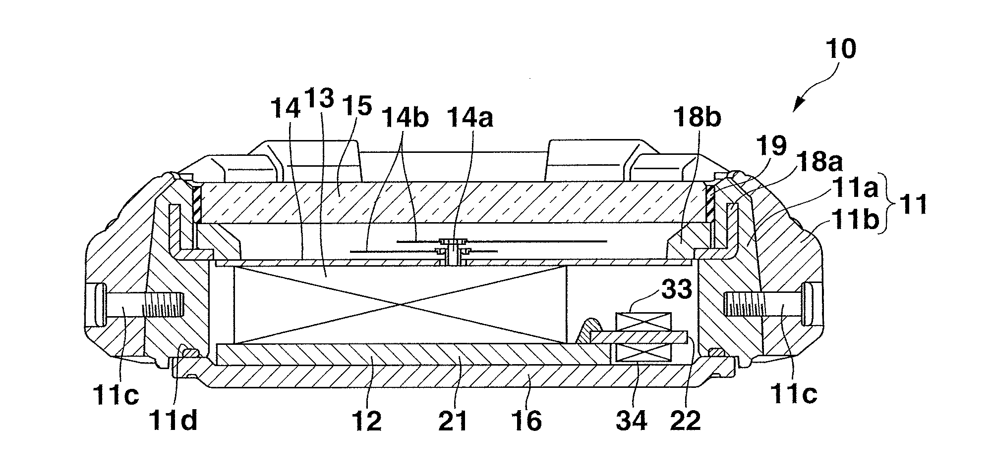
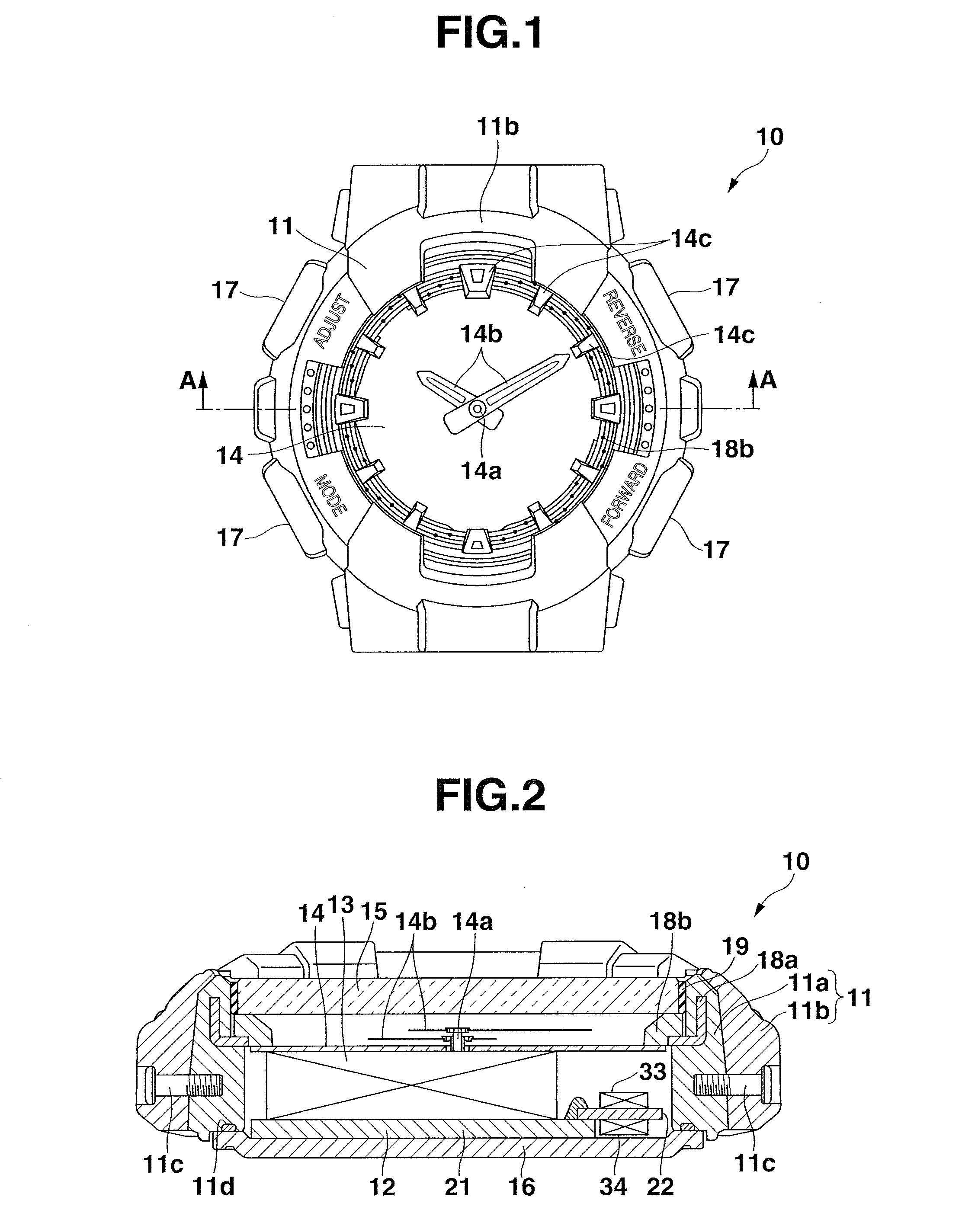
[0015]The following is an explanation of a configuration of a timepiece 10 according to a first embodiment of the present invention, with reference to FIG. 1 to FIG. 7. The drawings properly schematically illustrate the configuration in an enlarged or reduced manner, or with constituent elements omitted.

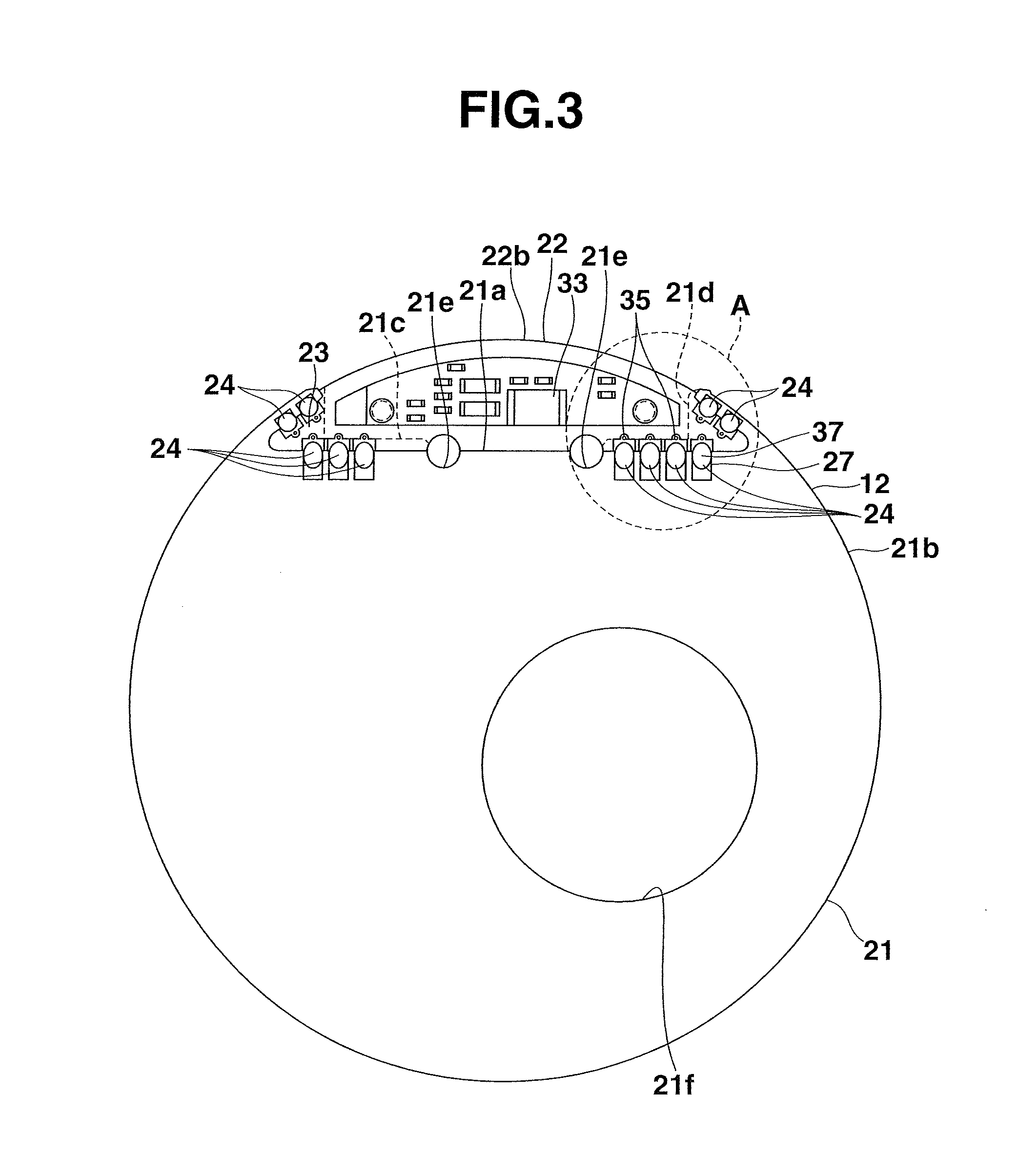
[0016]FIG. 1 is a plan view illustrating a configuration of the timepiece 10, and FIG. 2 is a cross-sectional view illustrating the configuration of the timepiece 10. FIG. 3 is a plan view illustrating a substrate structure of the timepiece 10, and FIG. 4 is an enlarged view of a part of FIG. 3. FIG. 5 is a cross-sectional view taken along line B-B of FIG. 4, and FIG. 6 is an exploded view of the substrate structure. FIG. 7 is a bottom view of a module substrate 22.

[0017]As illustrated in FIG. 1 and FIG. 2, the timepiece 10 is a wristwatch. The timepiece 10 comprises a wristwatch case 11 forming an outer frame, a substrate unit 12 serving as a substrate structure provided in the wris...


PUM

PropertyMeasurementUnit
center angleaaaaaaaaaa
circumferenceaaaaaaaaaa
outer circumferenceaaaaaaaaaa

Abstract

A substrate unit includes a first substrate and a second substrate, the second substrate including a superimposed portion superimposed on at least part of the first substrate, and bonding portions located in a plurality of positions at least defining a plane in the superimposed portion, the bonding portions bonded to the first substrate.

Description

CROSS-REFERENCE TO RELATED APPLICATION[0001]This application is based upon and claims the benefit of priority from the prior Japanese Patent Application No. 2015-039024, filed Feb. 27, 2015 the entire content of which is incorporated herein by reference.BACKGROUND OF THE INVENTION[0002]The present invention relate generally to a substrate unit, a timepiece, and a substrate bonding method.[0003]A technique is used for connecting a plurality of substrates that are used as a substrate structure for a watch or the like (for example, see Jpn. Pat. Appln. KOKAI Pub. No. 2007-227229). For example, a known substrate structure has a structure in which one substrate is superimposed on part of an upper surface of the other substrate, and the substrates are electrically and mechanically connected using a pair of connectors. For example, an entire circumference of one substrate is provided with a guide pin extending from the substrate surface toward the other opposed substrate, and the other sub...

Claims


Application Information

Patent Timeline
Patent Type & Authority Applications(United States)
IPC IPC(8): G04G21/00B23K1/00H05K1/11G04G17/04
CPCG04G21/00H05K1/115B23K1/0016G04G17/04G04B33/00H05K1/113H05K1/117H05K1/141H05K3/368H05K2201/09027H05K2201/09181G04G17/06
Inventor NAMIKI, KOJI
Owner CASIO COMPUTER CO LTD
Why Eureka
Try Eureka