
Ink jet printing apparatus and method for controlling inkjet printing apparatus

a technology of inkjet printing and ink jet, which is applied in the field of inkjet printing apparatus, can solve the problems of printers that printers that print images on wide print media are likely to suffer from the situation, and printers are likely to be subjected to defective ink ejection, so as to reduce the defective ejection of ink and increase the ink ejection power

Active Publication Date: 2016-11-24
CANON KK
View PDF10 Cites 1 Cited by
  • Summary
  • Abstract
  • Description
  • Claims
  • Application Information

AI Technical Summary

Benefits of technology

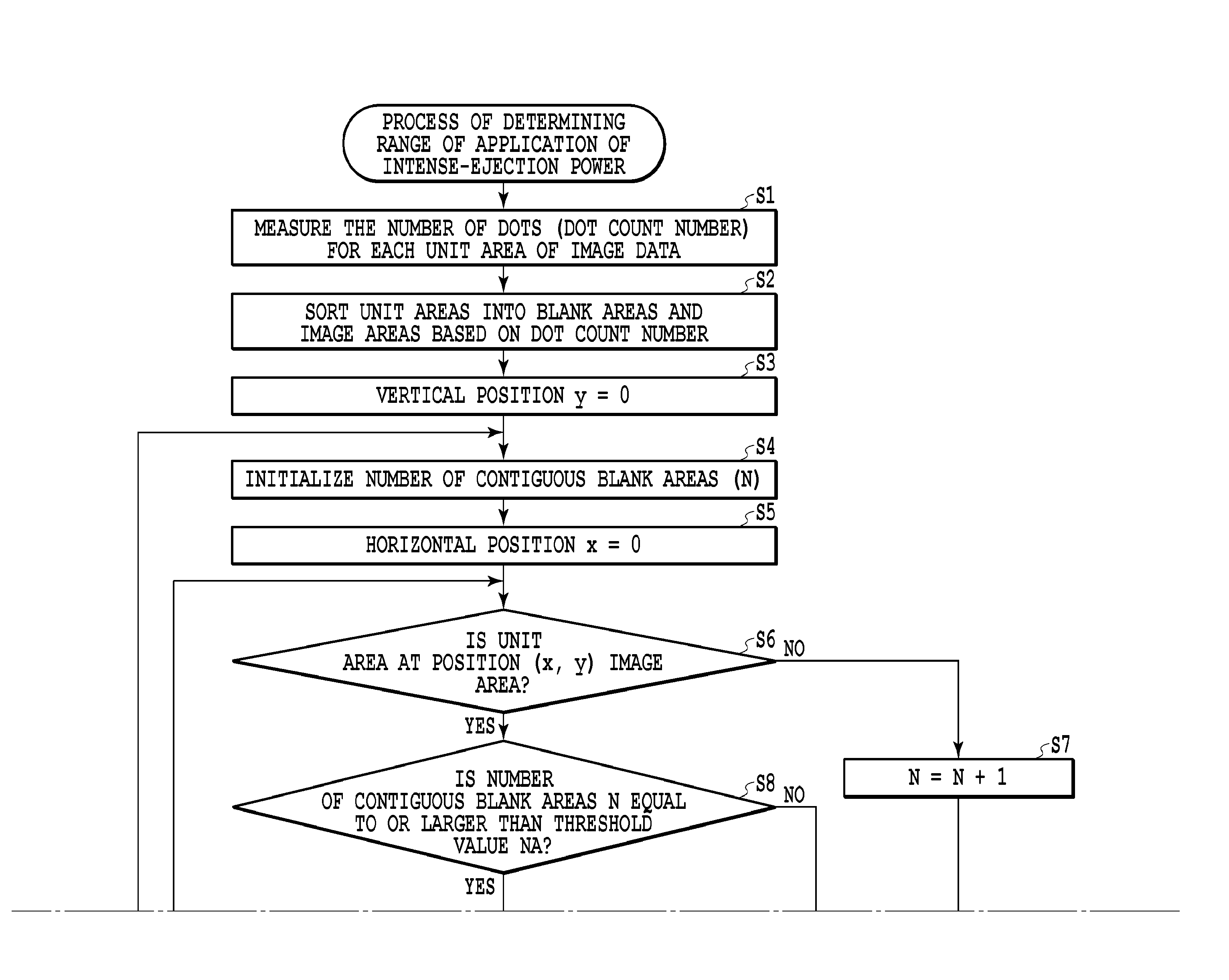
The invention provides an ink jet printing apparatus that can increase the amount of ink ejected from its nozzles, even if some of them have not been used for a long time. This is done by dividing the print elements into multiple groups, allowing for optimal timing for increasing the power of the ink ejection. This results in better quality printing, consistently and with fewer defective nozzles.

Problems solved by technology

In an inkjet printing apparatus, if no ink has been ejected from nozzles of a print head for a long time, ink remaining near the nozzles may be dried or thickened, leading to defective ink ejection.
In particular, a large-sized printer which prints images on wide print medium is likely to suffer from the situation in which no ink has been ejected from nozzles of a print head for along time.
Correspondingly, such a printer is likely to be subjected to defective ink ejection.
However, depending on a printed image, only some of the nozzles may not eject ink for a long time and may thus be caused to eject ink defectively.
If some of the nozzles thus eject ink defectively, the density of the printed image may be uneven.
Thus, it is difficult to detect when only some nozzles have not ejected ink for a long time.
Therefore, it is difficult to reliably suppress the defective ejection of ink from the nozzles simply by temporarily increasing the driving power for the print head when the no image area changes to the image area.

Method used


Image

  • Ink jet printing apparatus and method for controlling inkjet printing apparatus
  • Ink jet printing apparatus and method for controlling inkjet printing apparatus
  • Ink jet printing apparatus and method for controlling inkjet printing apparatus

Examples


Embodiment Construction

[0035]An embodiment of the present invention will be described below based on the drawings.

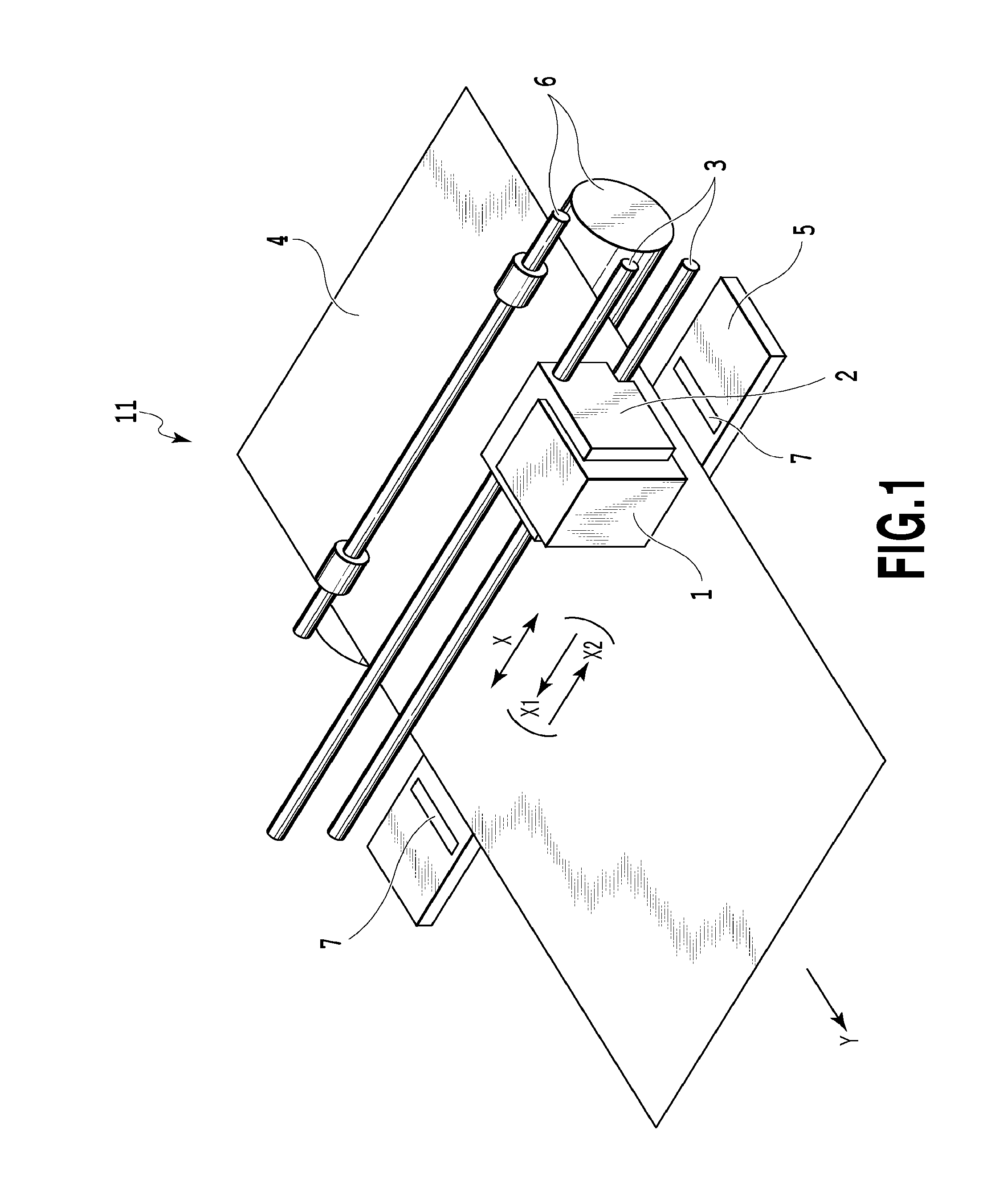
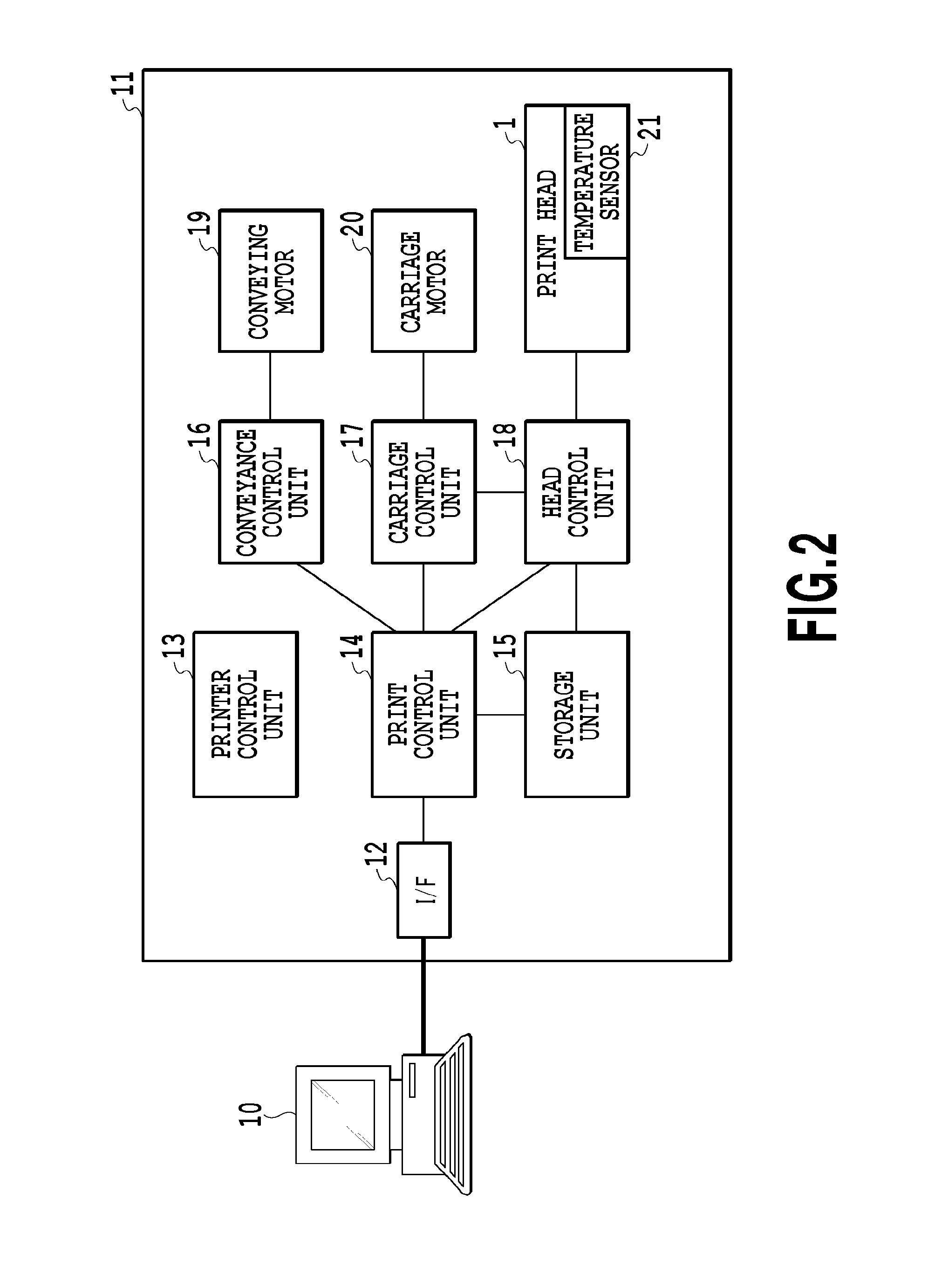
[0036]FIG. 1 is a schematic perspective view of a serial ink jet printing apparatus (ink jet printer) 11 to which the present invention is applied. A print head 1 is mounted on a carriage 2, and the carriage 2 moves along a guide shaft 3 in a main scan direction shown by arrow X. During printing of an image, the print medium 4, supported on a platen 5, is intermittently conveyed in a sub-scan direction shown by arrow Y. The serial printing apparatus 11 as in the present example prints an image on the print medium 4 by repeating an operation of conveying the print medium 4 in the sub-scan direction and an operation of allowing the print head 1 to eject ink while moving the print head 1 and the carriage 2 in the main scanning direction. In the main scan direction, the right side in FIG. 1 is defined as a reference side, and the left side in FIG. 1 is defined as a non-reference side. Forward prin...


PUM


Abstract

An ink jet printing apparatus is provided which can suppress defective ejection of ink from the nozzles. An element array with a plurality of print elements arranged therein is divided into a plurality of groups of print elements. For each of the plurality of groups, the apparatus determines whether any area undergoes a failure to perform a normal printing operation. If the apparatus determines, for any of the plurality of groups, that any area is likely to undergo the failure, when the print medium is printed based on the print data corresponding to the area, control is performed in such a manner that a first amount of energy supplied to drive one print element is greater than a second amount of energy supplied to drive one print element immediately before the print medium is printed based on the print data corresponding to the area.

Description

BACKGROUND OF THE INVENTION[0001]Field of the Invention[0002]The present invention relates to an ink jet printing apparatus and a method for controlling an ink jet printing apparatus for printing an image while moving a print head capable of ejecting ink.[0003]Description of the Related Art[0004]In an inkjet printing apparatus, if no ink has been ejected from nozzles of a print head for a long time, ink remaining near the nozzles may be dried or thickened, leading to defective ink ejection. In particular, a large-sized printer which prints images on wide print medium is likely to suffer from the situation in which no ink has been ejected from nozzles of a print head for along time. Correspondingly, such a printer is likely to be subjected to defective ink ejection.[0005]Japanese Patent Laid-Open No. 2008-55855 describes a method for setting driving power (the ink ejection power of nozzles) for a print head according to the scan position of the print head in order to suppress defecti...

Claims


Application Information

Patent Timeline
Patent Type & Authority Applications(United States)
IPC IPC(8): B41J2/045
CPCB41J2/04573B41J2/04586B41J2/04598B41J2/2139B41J2/04563B41J2/0458B41J2/0459B41J2/04591B41J2/04548
Inventor KATSUURA, JOJI
Owner CANON KK
Learn More