Biomimic design stabilizing fin or keel for surface planing or submerged watercraft

a technology of stabilizing fins and keels, which is applied in the direction of waterborne vessels, special purpose vessels, underwater equipment, etc., can solve the problems of limited functionality of devices and loss of control of watercraft by operators

Active Publication Date: 2016-12-08
RICHENBERG RANDAL
View PDF1 Cites 0 Cited by
  • Summary
  • Abstract
  • Description
  • Claims
  • Application Information

AI Technical Summary

Problems solved by technology

At the point when a fin or keel produces cavitating flow the fin or keel loses the ability to provide dimensional stability resulting in the loss of con...

Method used


Image

  • Biomimic design stabilizing fin or keel for surface planing or submerged watercraft
  • Biomimic design stabilizing fin or keel for surface planing or submerged watercraft
  • Biomimic design stabilizing fin or keel for surface planing or submerged watercraft

Examples


Embodiment Construction

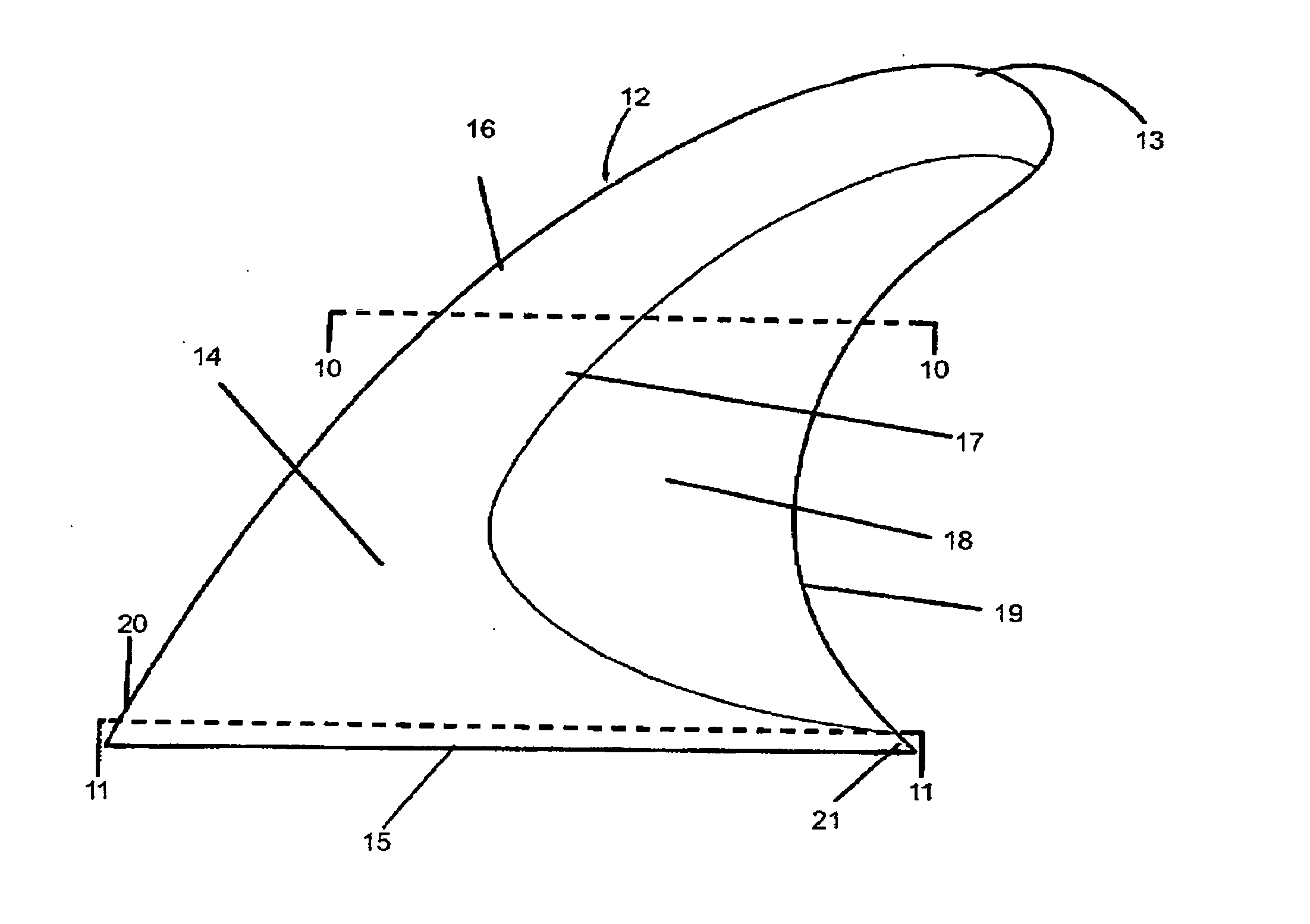
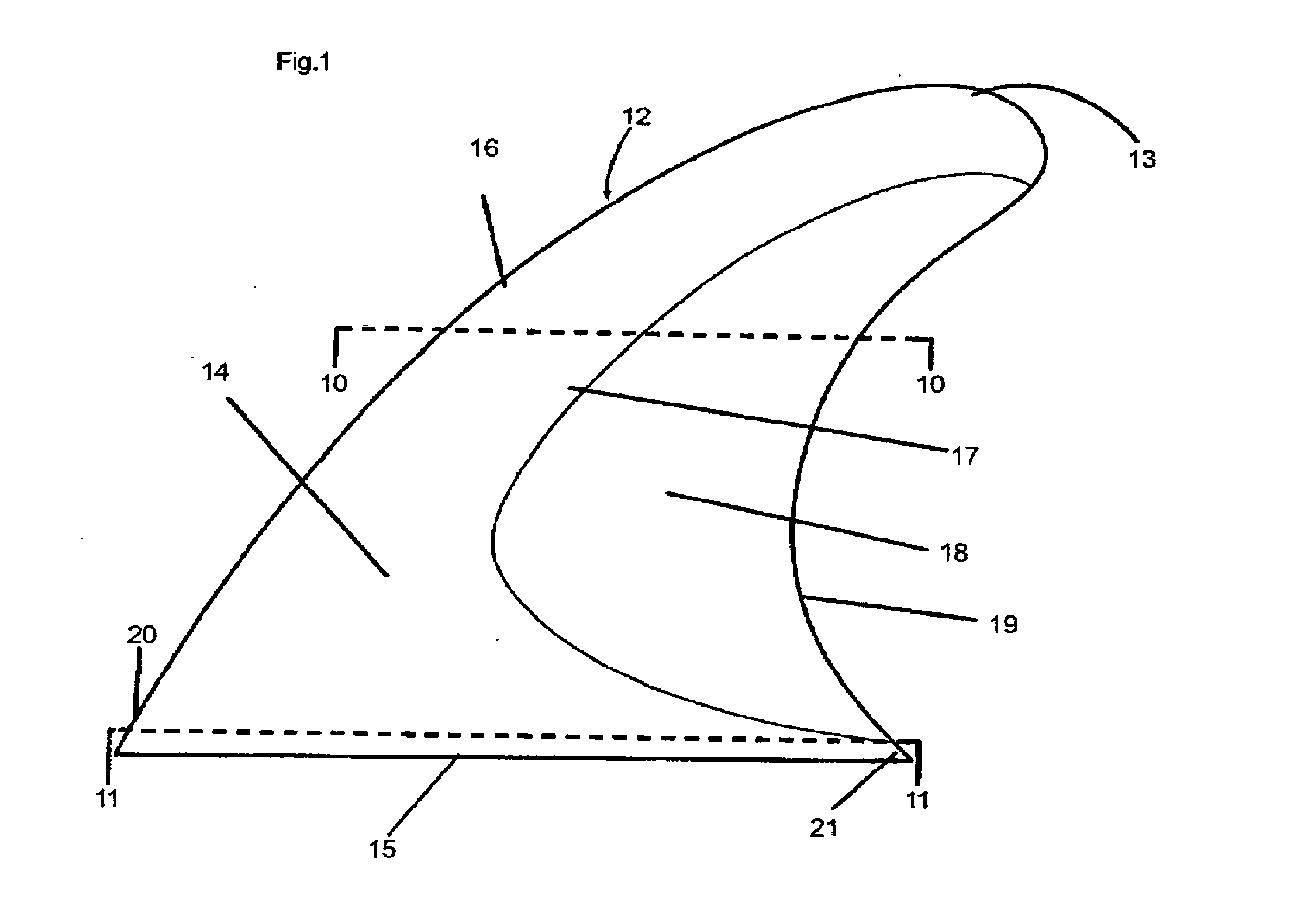
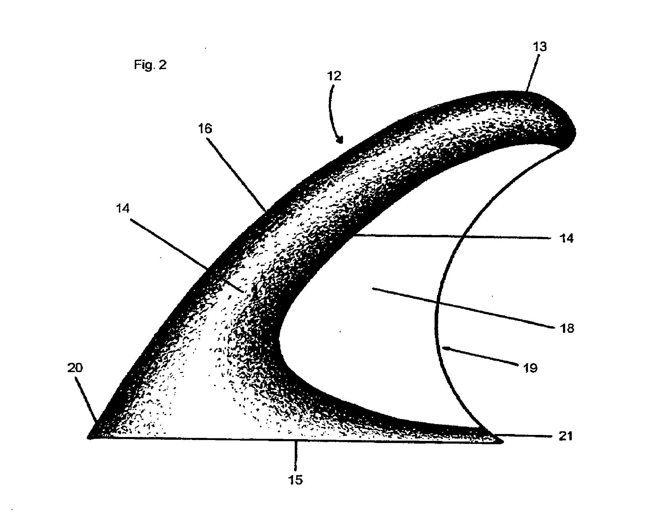
[0009]The present invention relates to fins and keels that are utilized for dimensional stability and control of watercraft in motion planing on water surface or submerged.

[0010]The present invention improves on current fin or keel designs by utilizing a thin flexible element positioned in the rear trailing edge area of fin or keel and providing leading edge to trailing edge lateral flex to fin or keel providing increased stability, control and efficiency of a surface planing or submerged watercraft in motion by reducing a fin or keels development of a cavitating flow in the laminar flow boundary, reducing turbulence in laminar flow exiting a fin or keel and reducing fin or keel weight. Cavitating flow occurs when water pressure or hydrodynamic pressure increases on the inner radius side of a fin or keel and decreases on the outer radius side of fin or keel during directional changes (i.e. turns or tacks). When the water pressure or hydrodynamic pressure becomes too great on the inn...


PUM


Abstract

A stabilizing fin or keel utilizing biomimic design features for use on surface planing or submerged watercraft to provide increased dimensional stability, control and efficiency.

Description

FIELD OF INVENTION[0001]The invention as presented relates to surface planing or submersible watercraft such as surfboards, kiteboards, sailboats, submersible craft, etc. and more specifically to fins or keels employed for dimensional stability and control of watercraft while in motion through water either on water surface or submerged.BACKGROUND OF INVENTION[0002]This invention relates to surface planing or submerged watercraft such as surfboards, kiteboards, sailboats, submersible craft, etc. and specifically to fins or keels of which the primary function of fins or keels attached to a watercraft surface that contacts water is to provide dimensional stability and control of watercraft while moving or propelled through water either on water surface or submerged. The present invention improves on existing designs by providing an increased area of lateral flex (leading edge to trailing edge) that is not featured in existing designs. The number, shape, size, and location of fins or ke...

Claims


Application Information

Patent Timeline
IPC IPC(8): B63B35/79B63G8/00
CPCB63G8/00B63B35/7926B63B32/62
Inventor RICHENBERG, RANDAL
Owner RICHENBERG RANDAL
Why Eureka
Try Eureka