
Pipe grooving device

Active Publication Date: 2016-12-29
LAROCHELLE TYSON +1
View PDF3 Cites 0 Cited by
  • Summary
  • Abstract
  • Description
  • Claims
  • Application Information

AI Technical Summary

Benefits of technology

The Grooving device is a tool that can be attached to a power drive and used to cut and groove pipes. It allows for easy positioning and support of pipes, and can handle long pieces of pipe. The device can be easily attached and removed from the power drive, allowing for easy replacement with different tools. The operator can also easily move the device to another location and start cutting and grooving new segments of pipe without needing to alter the power drive or tool assembly.

Problems solved by technology

This often results in a situation in which an additional operator has to hold the opposite end of a long piece of pipe as it is being grooved.
Should the operator then wish to cut the next section of pipe, the grooving tool has to be removed and the cut / ream / thread assembly reattached, creating a cumbersome process when an operator needs to cut and groove many pieces of pipe.

Method used


Image

  • Pipe grooving device
  • Pipe grooving device
  • Pipe grooving device

Examples


Embodiment Construction

[0035]The present invention will now be described more fully in detail with reference to the accompanying drawings, in which the preferred embodiments of the invention are shown. This invention should not, however, be construed as limited to the embodiments set forth herein; rather, they are provided so that this disclosure will be complete and will fully convey the scope of the invention to those skilled in the art.

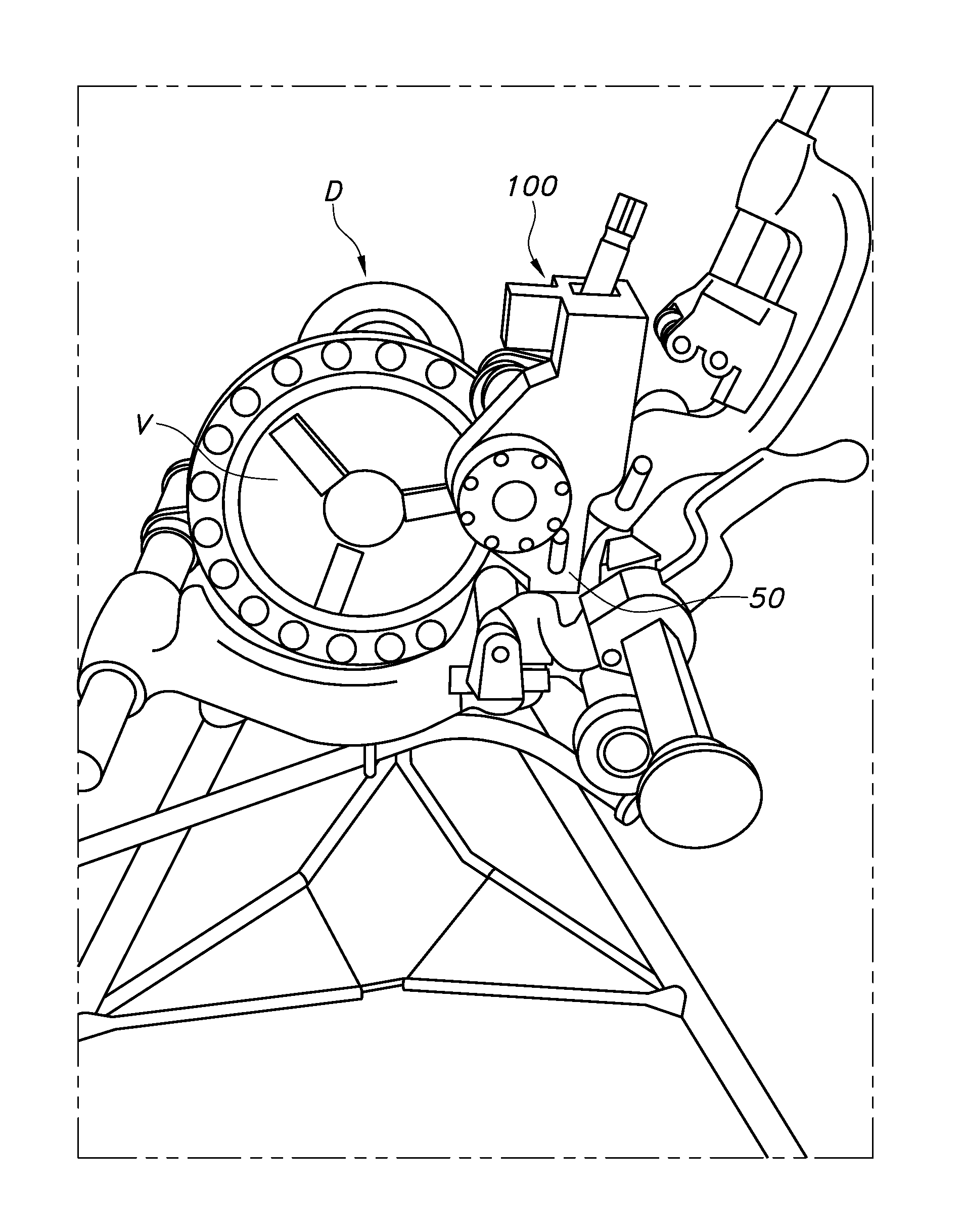
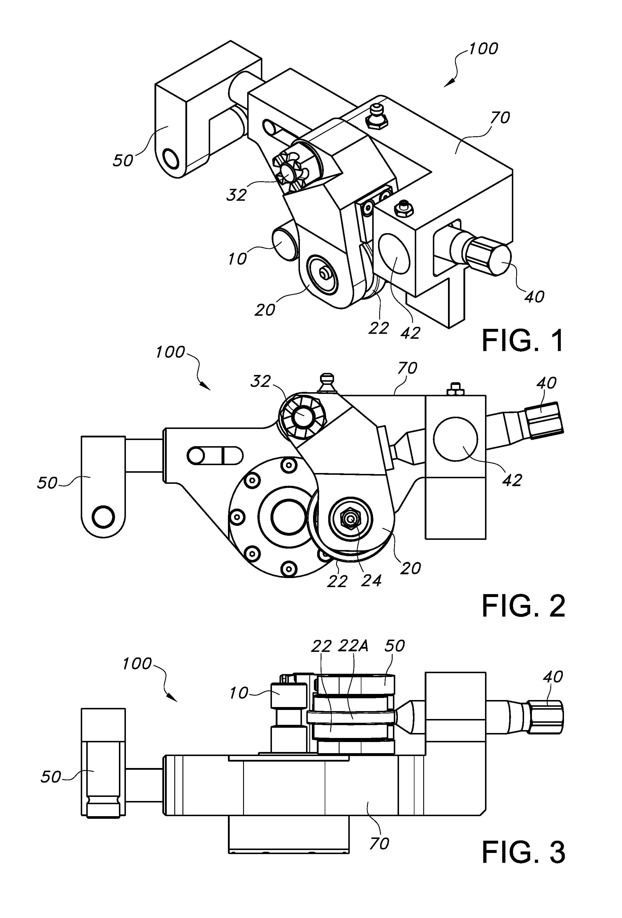
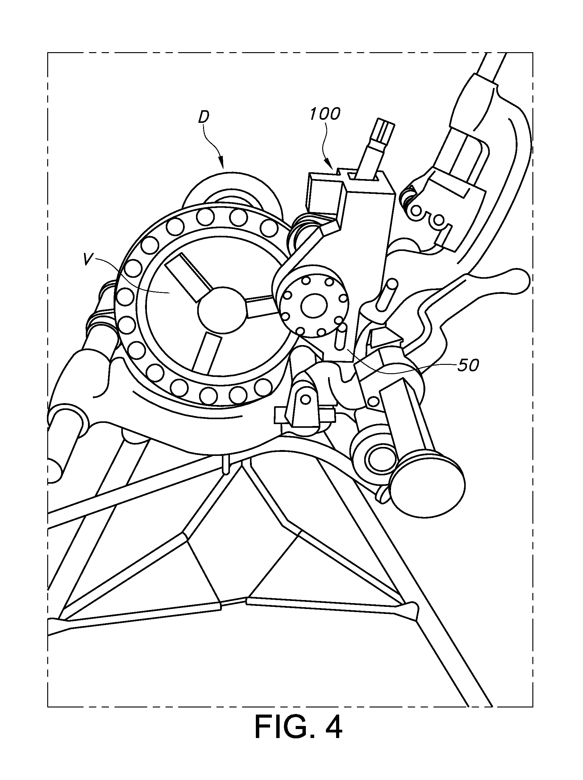
[0036]FIGS. 1, 2, and 3 illustrate a pipe grooving device 100 according to the invention that includes a groove shaft 10, a wheel housing assembly 20, an activation rod 40 and an attachment assembly 50, each contained in a device housing 70. The device 100 attaches to a power drive D, shown in FIGS. 4 and 5, by attachment assembly 50. A pipe P is inserted through the power drive D and placed over the groove shaft 10 and secured in the power drive D by a vice V.

[0037]Activating the power drive D causes the pipe P to rotate about the groove shaft 10. A user operates the ac...


PUM

PropertyMeasurementUnit
Pressureaaaaaaaaaa

Abstract

A pipe grooving tool that works with commercially-available power drives. The tool attaches to the power drive using the existing tool assembly on the power drive, and allows a single operator to cut, ream and groove multiple pipe segments, without having to replace tools or otherwise alter the power drive and its tool assembly between grooving different pipe segments.

Description

BACKGROUND INFORMATION[0001]1. Field of the Invention[0002]The invention relates to grooving tools, more specifically, a tool that can be used with an existing power drive for creating a groove on a pipe.[0003]2. Discussion of Prior Art[0004]Tools for cutting, threading and grooving pipes have been known for considerable time. Common power tools, such as the RIDGID 300 Power Drive, provide an assembly that combines tools for cutting, reaming and threading a pipe. Such tools are typically used by inserting a pipe through a center opening in the power drive and securing it in place by a vice. Actuating the drive causes the pipe to spin. A user then applies the cutting device to cut the pipe to the desired length, and then uses the reamer to remove the inside burrs. A threading die-head may then be used to thread the end of the pipe.[0005]If a user wishes to groove the pipe, he must remove the entire tool assembly and attach an external grooving tool that is used to create a groove on ...

Claims


Application Information

Patent Timeline
IPC IPC(8): B21D17/04
CPCB21D17/04
Inventor LAROCHELLE, TYSONBOSSE, GERARD
Owner LAROCHELLE TYSON
Learn More