Supercharge Your Innovation With Domain-Expert AI Agents!

Telescopic suitcase handle

a technology of telescopic handles and locking mechanisms, which is applied in the direction of luggage, other accessories, travelling accessories, etc., can solve the problems of designers unable to use narrow, thin, solid, or substantially open telescopic handles

Active Publication Date: 2017-01-05
TUMI INC
View PDF8 Cites 1 Cited by
  • Summary
  • Abstract
  • Description
  • Claims
  • Application Information

AI Technical Summary

Benefits of technology

This patent describes a telescopic suitcase handle which has several parts: a telescopic handle housing, a lower extended handle section, a spring-loaded protrusion, a button, an upper extended handle section, and a spring-loaded bullet. These components work together to hold the handle in different positions and allow it to move smoothly. Additionally, there are variations of this design that can also incorporate a recessed handle housing and/or ornamental cutouts. Overall, this technology improves the functionality and durability of telescopic suits handles while maintaining their appearance.

Problems solved by technology

The technical problem addressed in this patent relates to improving the design of telescopic luggage handles, specifically eliminating the requirement for internal hardware like cables and buttons to control the movement of the handle.

Method used


Image

  • Telescopic suitcase handle
  • Telescopic suitcase handle
  • Telescopic suitcase handle

Examples


Embodiment Construction

[0057]Reference will now be made in detail to representative examples illustrated in the accompanying drawings. It should be understood that the following descriptions are not intended to limit the examples to one preferred example. To the contrary, it is intended to cover alternatives, modifications, and equivalents as may be included within the spirit and scope of the described examples as defined by the appended claims.

[0058]As disclosed herein, the devices and methods presented can be used for a telescopic suitcase handle that provides a new locking mechanism that is controlled without the need for a button on the handle or gripping portion of a telescopic handle and without the need for a cable or similar hardware located along the interior of a telescopic handle.

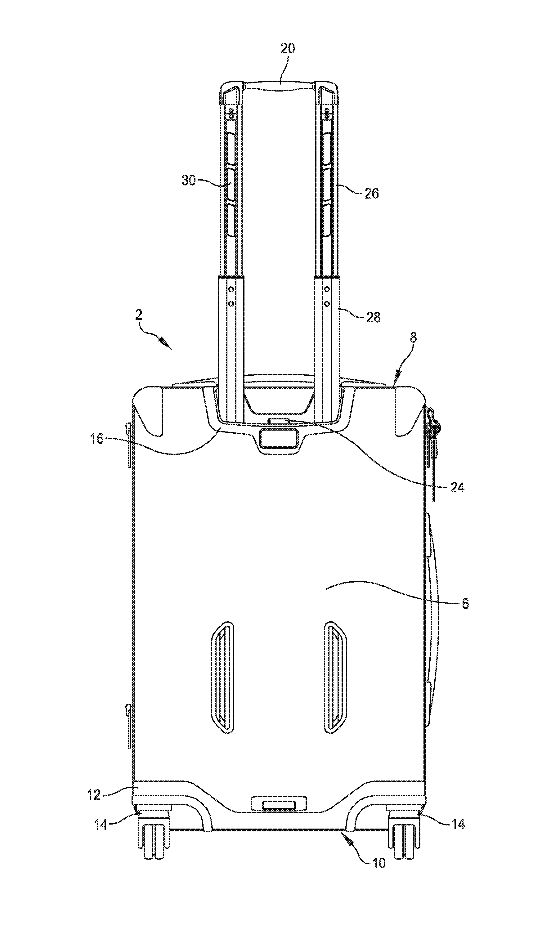
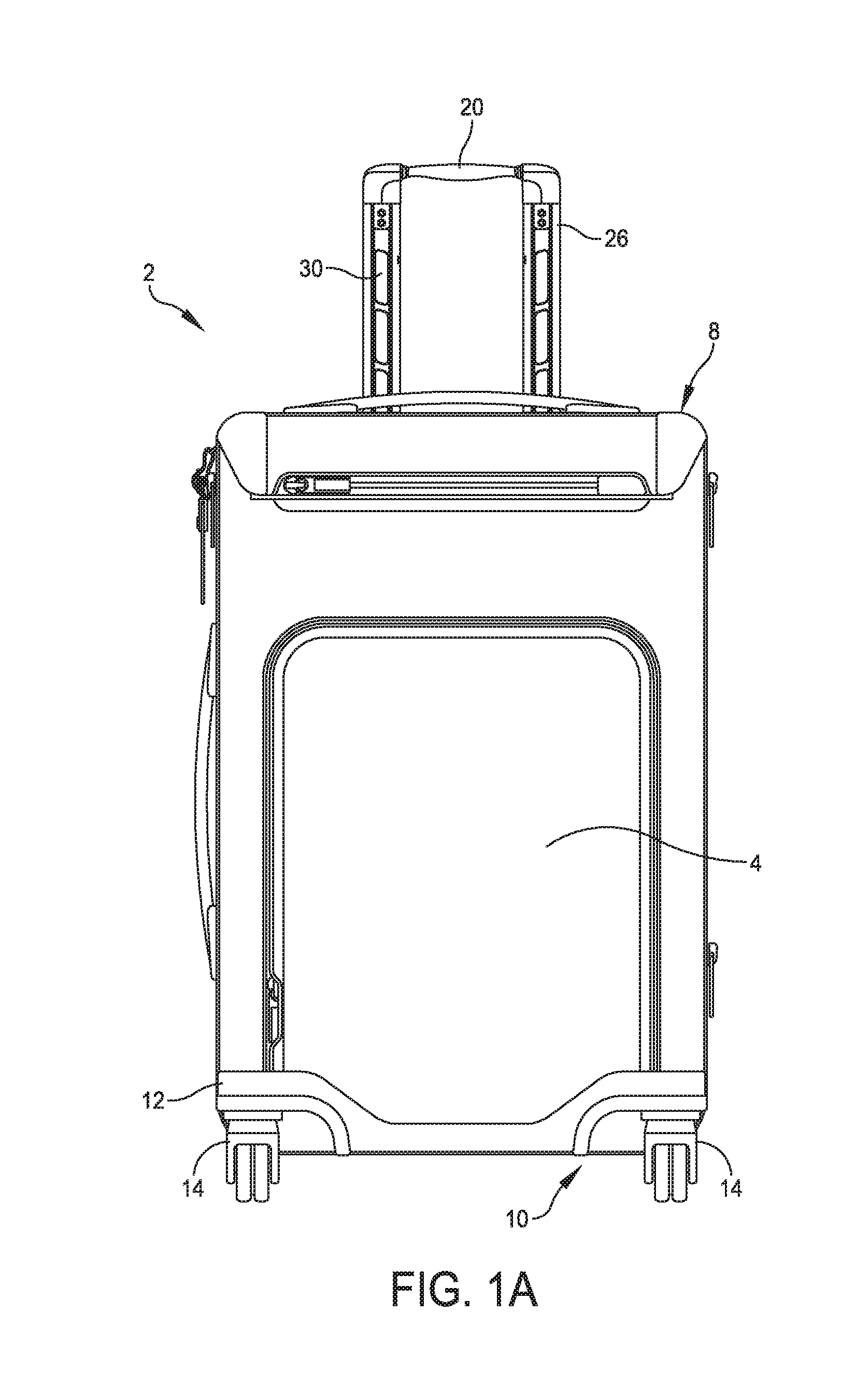
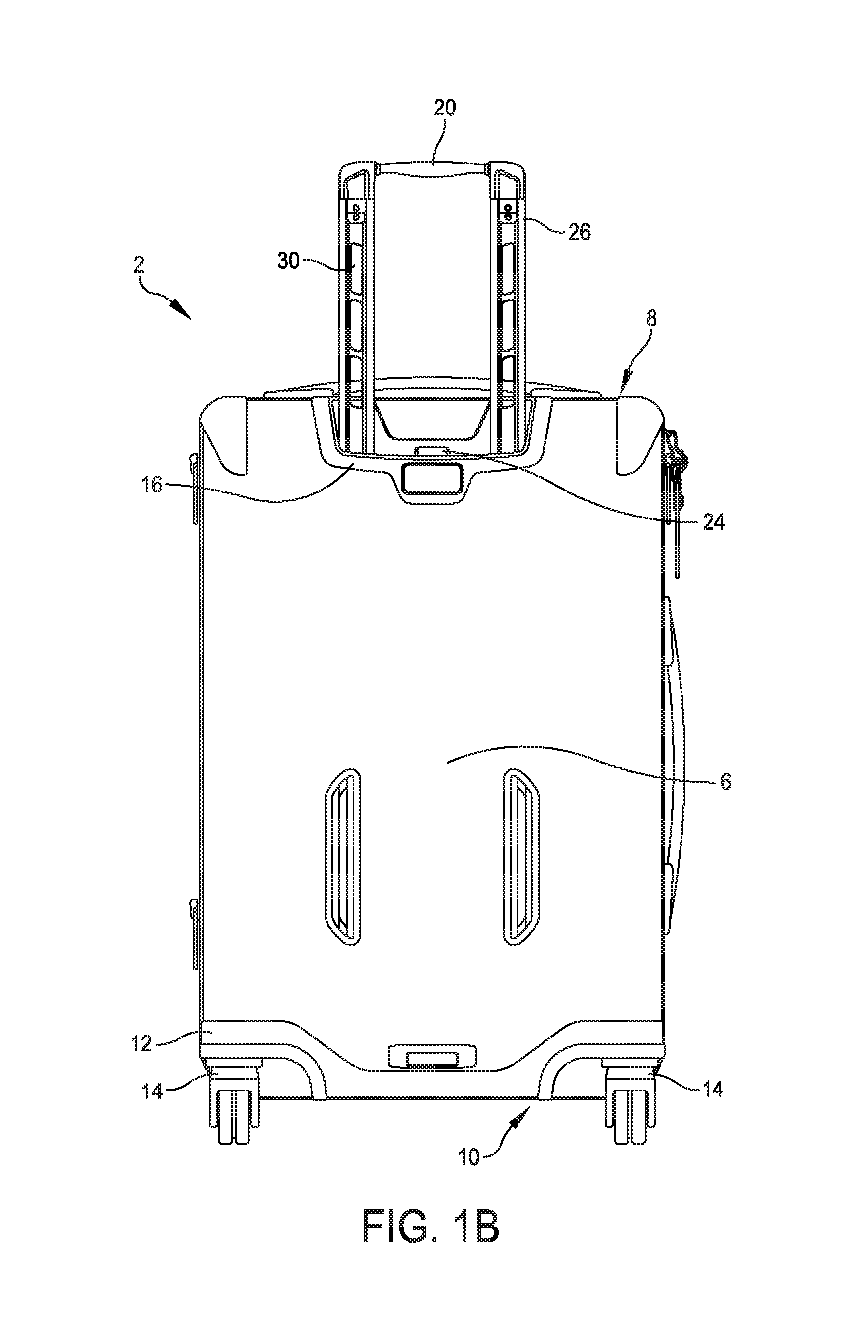
[0059]For the purpose of explanation and illustration, and not limitation, an example of a suitcase with a telescopic handle is shown in FIGS. 1A-1D. As illustrated, the suitcase 2 shown in FIGS. 1A-1D can be of any su...


PUM


Abstract

A telescopic suitcase handle is provided for including a telescopic handle housing disposed within a suitcase, a lower extendible handle section movably disposed within the telescopic handle housing, and an upper extendible handle section movably disposed within the lower section. A spring loaded bullet disposed within the upper section releasably engages with one of a plurality of openings along the length of the lower section for temporarily holding the upper extendible handle section in place. A spring-loaded protrusion releasably engages with the lower extendible handle section for temporarily holding the lower section in place.

Description


Claims


Application Information

Patent Timeline
Owner TUMI INC
Features
  • R&D
  • Intellectual Property
  • Life Sciences
  • Materials
  • Tech Scout
  • Unparalleled Data Quality
  • Higher Quality Content
  • 60% Fewer Hallucinations
Learn More