Hi-fi audio signal optical fiber cable

Inactive Publication Date: 2017-01-05
CHENG YU FENG
View PDF5 Cites 0 Cited by
  • Summary
  • Abstract
  • Description
  • Claims
  • Application Information

AI Technical Summary

Benefits of technology

The patent text describes a new type of optical fiber cable that is designed to transmit high-quality audio signals. The cable has a special design that allows for better reflection of the optical signal and reduces signal loss. This is achieved by creating a small gap between the optical fibers and the surrounding materials, which leads to better reflections. Additionally, the smaller numerical aperture of each optical fiber reduces the distance between them, which reduces signal loss. Overall, this new cable design ensures high-quality audio signals can be transmitted effectively.

Problems solved by technology

Suffering from electromagnetic and material wearing of ordinary cable lines, traditional analog audio signal transmission is likely to lose fidelity.
It is thus difficult to realize high fidelity on normal AV terminal devices.
Therefore, the optical signal transmitted in the single-core optical fiber 40 has a longer optical path, which in turn results in more attenuation.

Method used


Image

  • Hi-fi audio signal optical fiber cable
  • Hi-fi audio signal optical fiber cable
  • Hi-fi audio signal optical fiber cable

Examples


Embodiment Construction

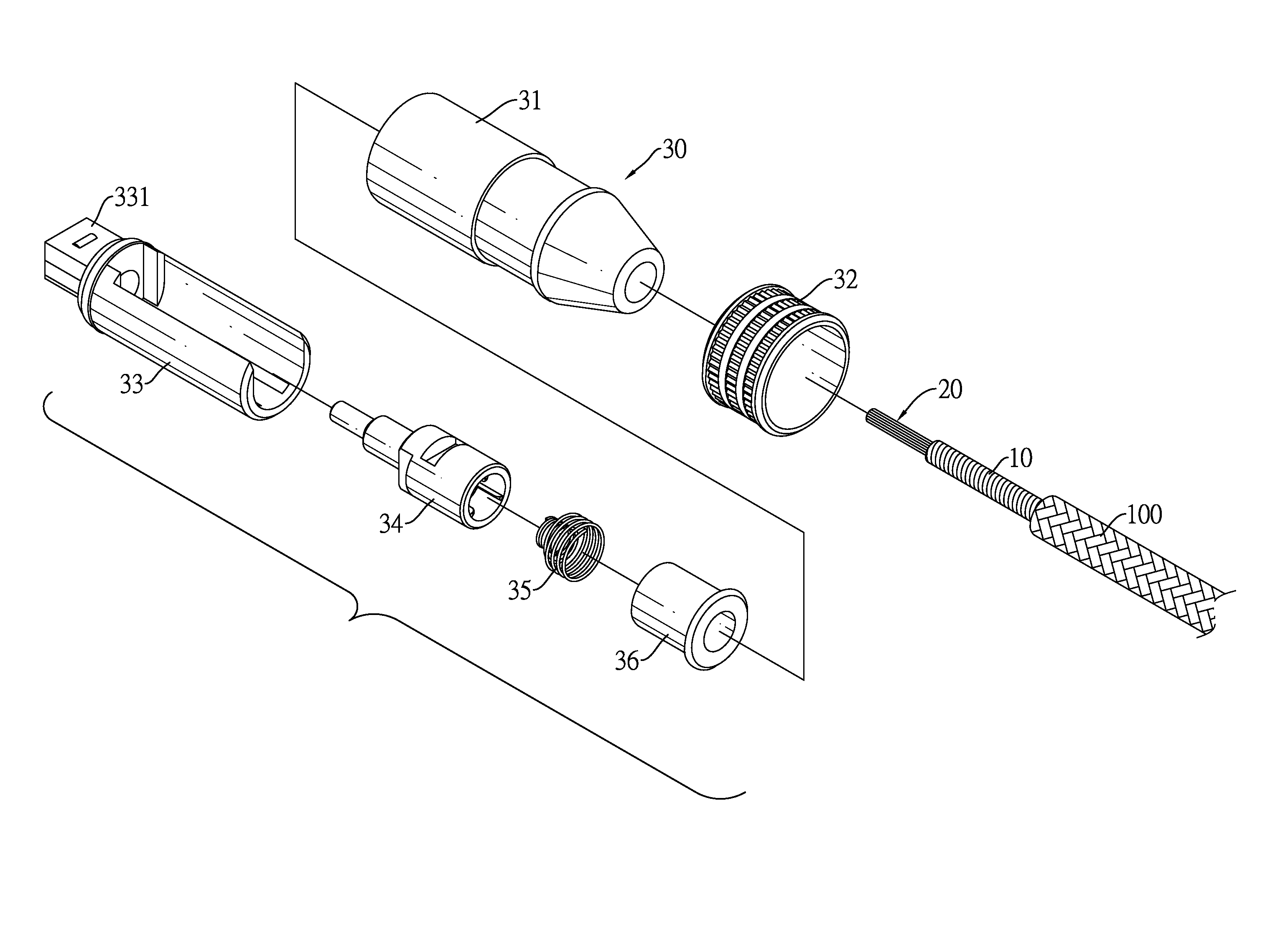
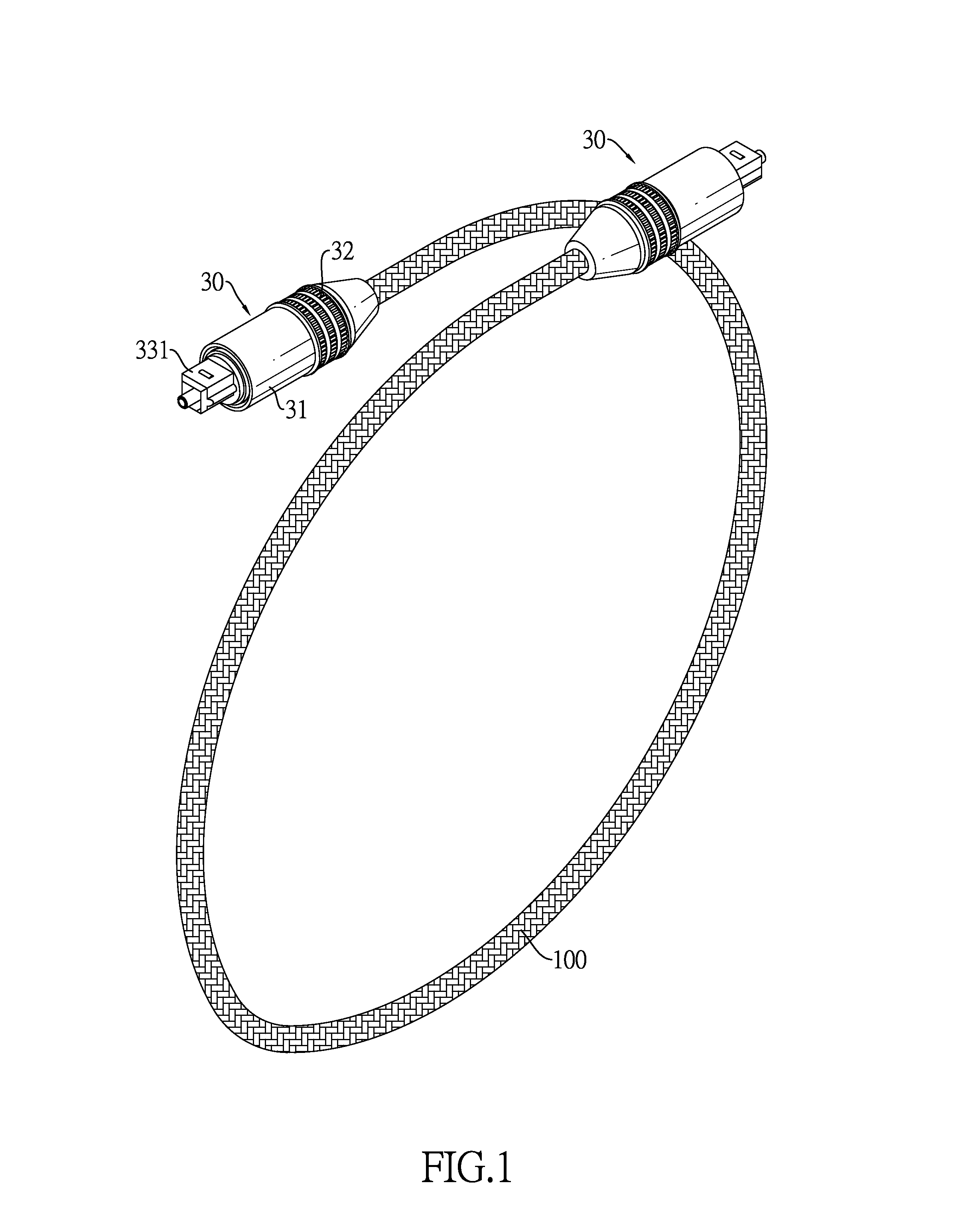
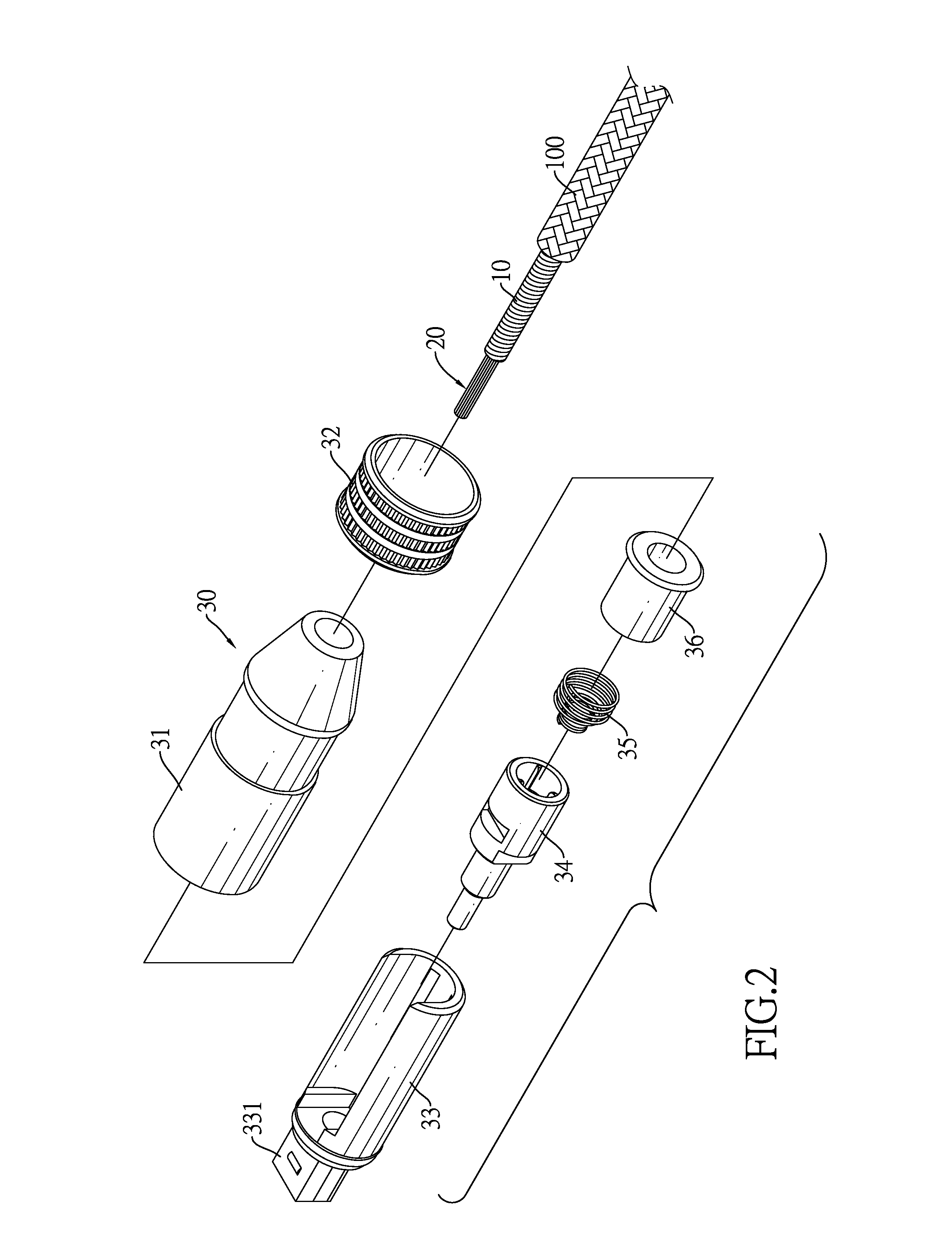
[0020]With reference to FIGS. 1 to 3, a Hi-Fi audio signal optical fiber cable comprises a snake tube 10, an optical fiber bundle 20, and two connectors 30. The snake tube 10 has two ends. Each of the two ends of the snake tube 10 has an opening with an inner diameter. The optical fiber bundle 20 has an outer diameter that is smaller than the inner diameter of the snake tube 10. In this embodiment, the snake tube 10 is formed by coiling a strip-shaped metal to have good flexibility and elasticity. Since it is made of metal, the snake tube 10 provides good protection for the optical fiber bundle 20 disposed therein, preventing the optical fiber bundle 20 from deformation or breaking due to squeezing or impacts. Moreover, the snake tube 10 is enclosed by a mesh cover 100 woven from a plastic material such as nylon.

[0021]The optical fiber bundle 20 is inserted coaxially inside the snake tube 10. As the outer diameter of the optical fiber bundle 20 is smaller than the inner diameter of ...


PUM


Abstract

A Hi-Fi audio signal optical fiber cable has an optical fiber bundle provided coaxially inside a snake tube. The optical fiber bundle has multiple optical fibers. Both ends of the optical fiber bundle protrude from the snake tube and are installed with a connector respectively. An air gap is formed between the optical fiber bundle and the snake tube so that ordinary air fills in the air gap. When a signal source inputs an optical signal via one connector, the optical signal is transmitted within each optical fiber by total reflection and goes out from the other connector. Since the refractive indices of the optical fiber bundle and the air have a significant difference, the total reflection is better, thereby achieving high fidelity. Each optical fiber has a smaller numerical aperture, and the optical path of the optical signal is shorter and signal attenuation in the material is avoided.

Description

BACKGROUND OF THE INVENTION[0001]1. Field of the Invention[0002]The invention relates to an optical fiber cable and, in particular, a Hi-Fi audio signal optical fiber cable that has an optical fiber bundle and an air gap filled with atmospheric air to increase the rate of total reflection.[0003]2. Description of Related Art[0004]As manufacturers of electronic products advocate the evolution of digital homes, people have higher demands about high-quality audio-video (AV) signals. Industries and markets of AV capture devices (single-lens cameras, video recorders, audio recorder, etc.), AV processing devices (personal computers, cloud servers, etc.), and AV output devices (high definition digital televisions) become prosperous. Suffering from electromagnetic and material wearing of ordinary cable lines, traditional analog audio signal transmission is likely to lose fidelity. It is thus difficult to realize high fidelity on normal AV terminal devices. Therefore, SONY, Philips, and other...

Claims


Application Information

Patent Timeline
IPC IPC(8): G02B6/40G02B6/44G02B6/06
CPCG02B6/443G02B6/4415G02B6/40G02B6/06
Inventor CHENG, YU-FENG
Owner CHENG YU FENG
Why Eureka
Try Eureka