
Coupler for power line communication and power-over-ethernet

a technology of power line communication and coupler, which is applied in the direction of power distribution line transmission, data switching details, data switching networks, etc., can solve the problems of weight, installation cost, maintenance cost,

Active Publication Date: 2017-02-09
THE BOEING CO
View PDF13 Cites 35 Cited by
  • Summary
  • Abstract
  • Description
  • Claims
  • Application Information

AI Technical Summary

Benefits of technology

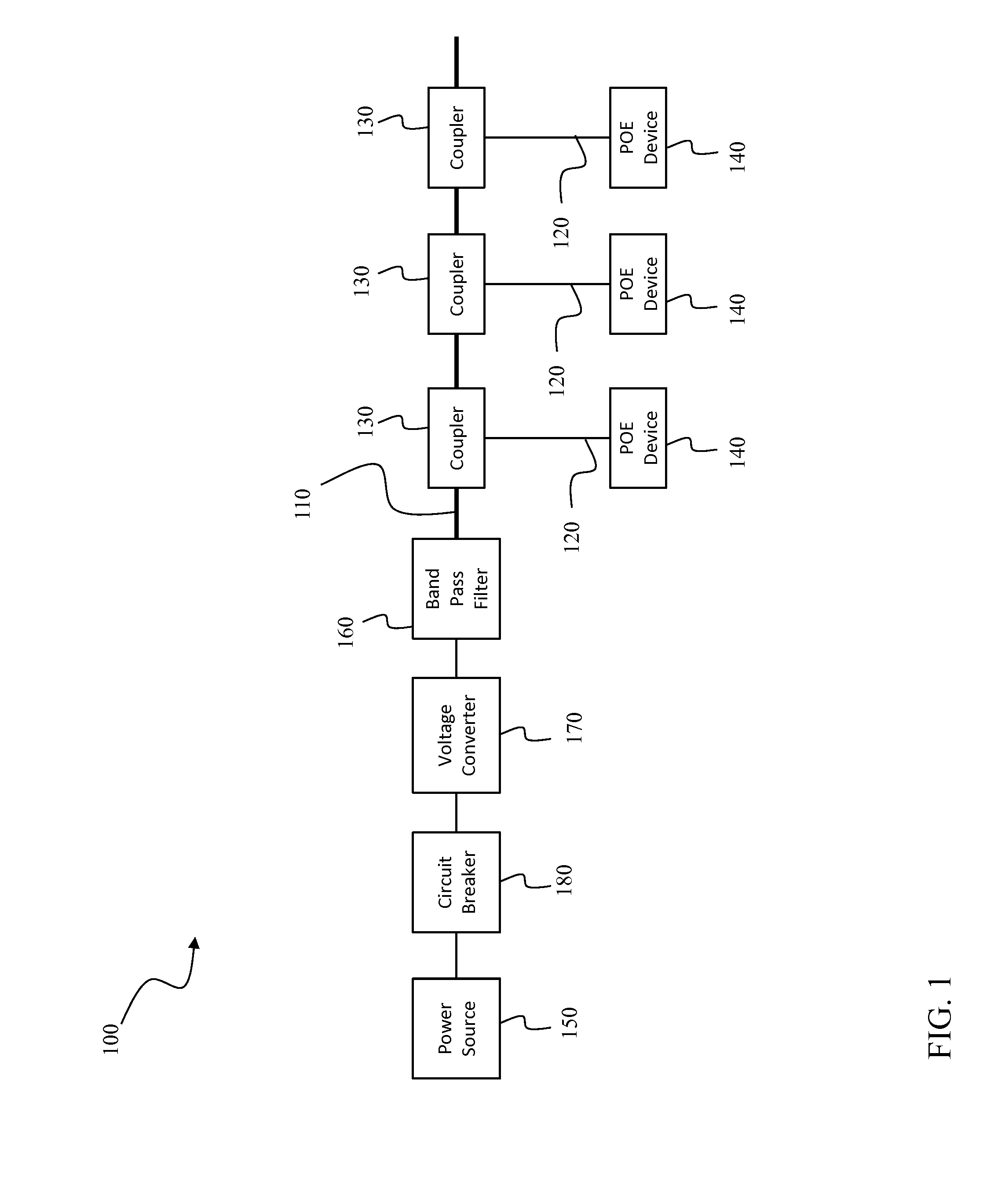
This patent describes a coupler that can connect a power line to an Ethernet network, allowing for the transfer of power and communication between devices. The coupler includes a transformer to condition the Ethernet signals for power-over-Ethernet transmission. The system also includes a power sourcing circuit to provide power to the coupler and a method to limit current conductance through the coupler. The technical effects of this invention include enabling seamless coupling of power and communication between devices, increased efficiency, and improved safety.

Problems solved by technology

However, in certain applications, such as aircraft, for example, additional wiring is installed at the expense of weight, installation cost, and maintenance cost.

Method used


Image

  • Coupler for power line communication and power-over-ethernet
  • Coupler for power line communication and power-over-ethernet
  • Coupler for power line communication and power-over-ethernet

Examples


Embodiment Construction

[0011]As used herein, an element or step recited in the singular and proceeded with the word “a” or “an” should be understood as not excluding plural elements or steps unless such exclusion is explicitly recited. Furthermore, references to “one embodiment” of the present invention or the “exemplary embodiment” are not intended to be interpreted as excluding the existence of additional embodiments that also incorporate the recited features.

[0012]Power-over-Ethernet (POE) is a technology used to deliver electrical power and data over Ethernet cabling. Power may be carried on dedicated power conductors, or together with data. For example, in 10Base-T, two twisted-pairs are used for data, leaving the others for power transmission. When power and data share conductors, power can be transmitted by a common-mode voltage applied to each twisted-pair. A POE device extracts the power using a center tap of an Ethernet pulse transformer. POE techniques are partially standardized in IEEE 802.3, ...


PUM


Abstract

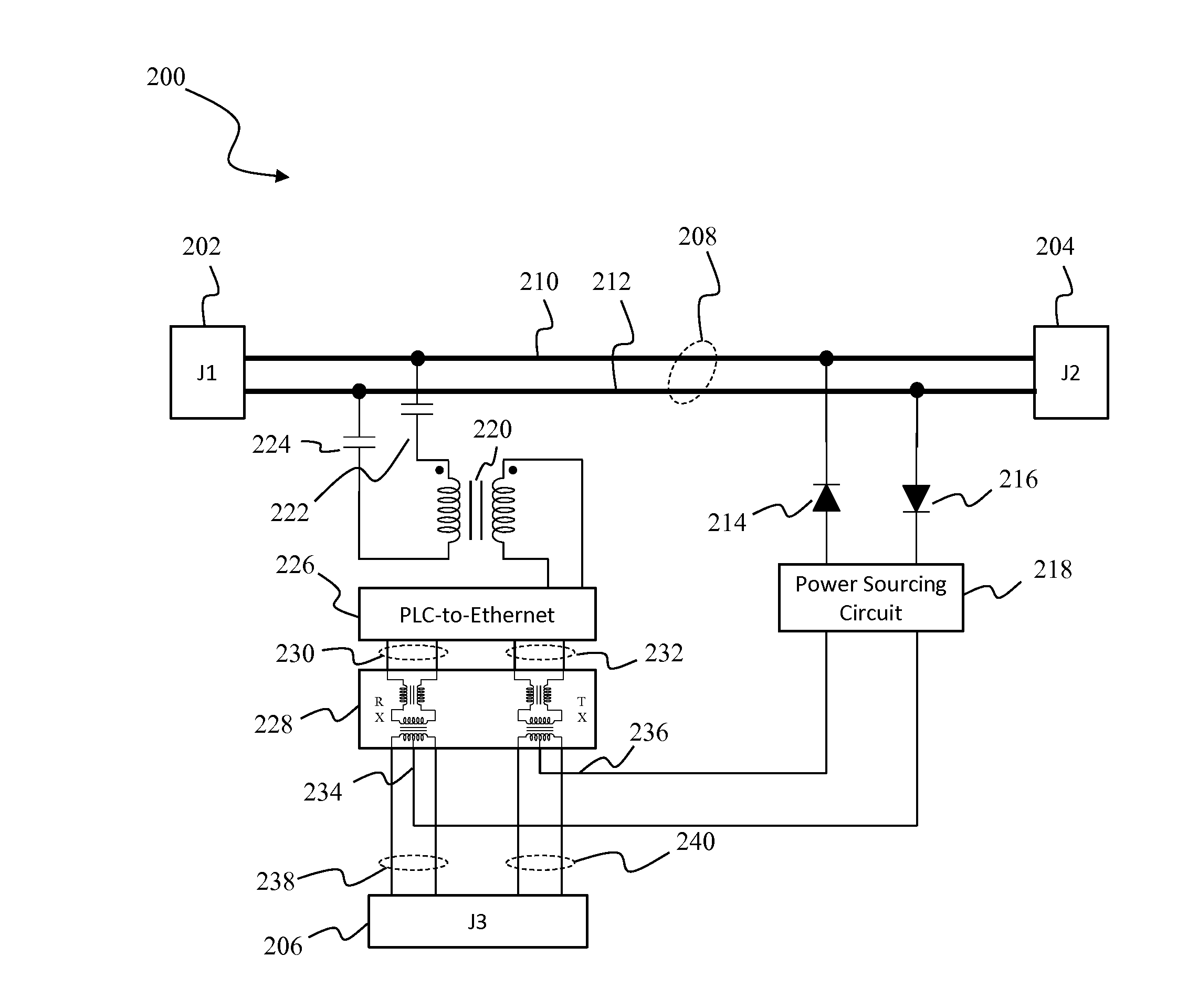
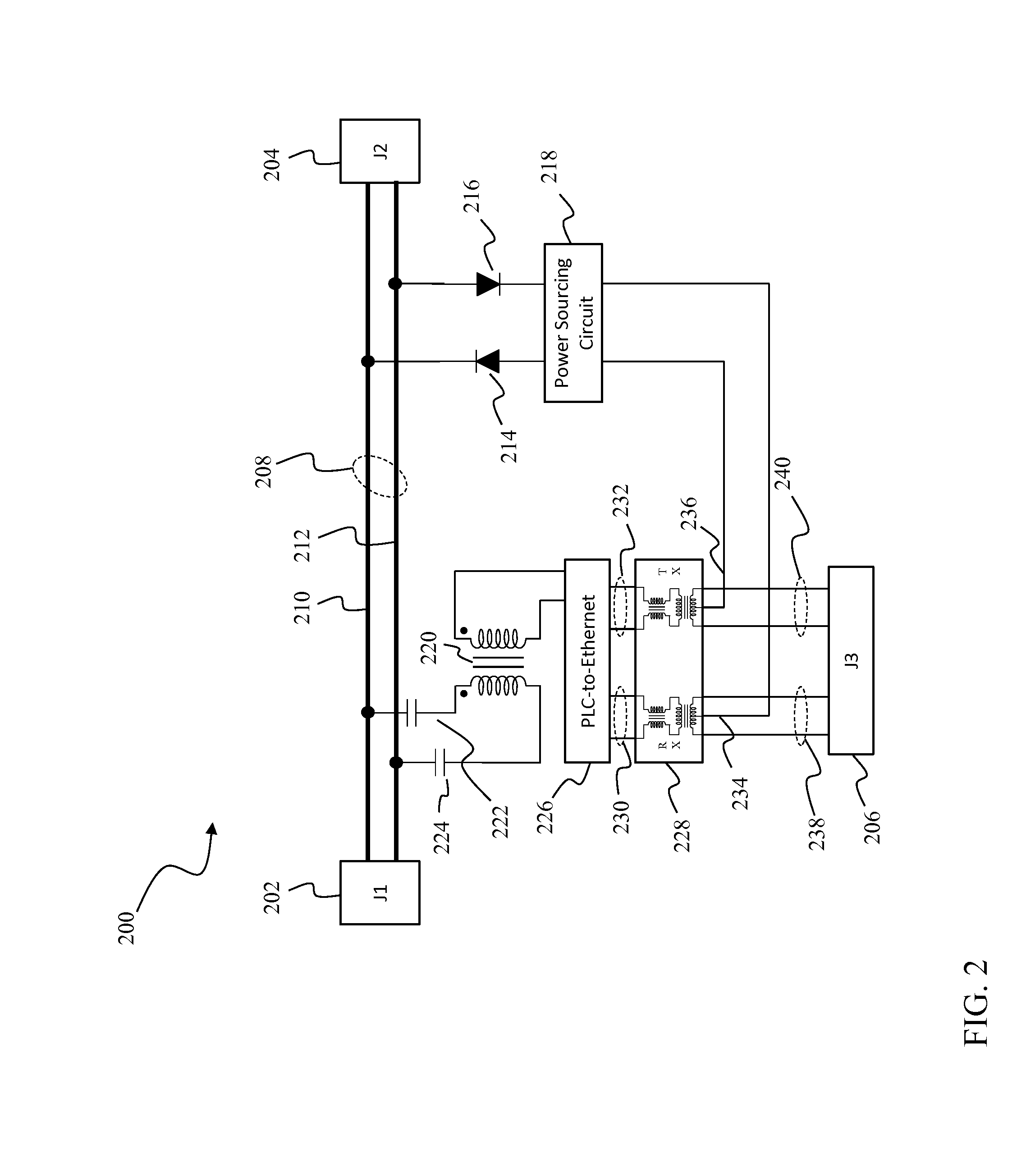
A coupler is provided. The coupler includes a power line, a PLC-to-Ethernet converter, a first transformer, and a power sourcing circuit. The power line is coupled between a first connector and a second connector. The power line is configured to conduct PLC signals. The PLC-to-Ethernet converter is configured to convert between the PLC signals and Ethernet signals. The first transformer is coupled between the PLC-to-Ethernet converter and a third connector. The first transformer is configured to condition the Ethernet signals for power-over-Ethernet transmission. The power sourcing circuit is coupled to the power line and configured to provide power to the first transformer.

Description

BACKGROUND[0001]The field of the disclosure relates generally to power distribution and communication buses and, more specifically, to a power line communication to power-over-Ethernet coupler.[0002]Many electrical systems utilize both a power distribution system and a communication system. These systems are often independently operated over distinct conductors, which generally requires installation of both power distribution wiring and communication wiring. In many applications the installation of separate power distribution and communication wiring is practical. However, in certain applications, such as aircraft, for example, additional wiring is installed at the expense of weight, installation cost, and maintenance cost.BRIEF DESCRIPTION[0003]According to one aspect of the present disclosure, a coupler is provided. The coupler includes a power line, a PLC-to-Ethernet converter, a first transformer, and a power sourcing circuit. The power line is coupled between a first connector ...

Claims


Application Information

Patent Timeline
Patent Type & Authority Applications(United States)
IPC IPC(8): H04L12/10H04L12/24H02J3/02
CPCH04L12/10H04L41/0659H02J3/02H04B3/56H04B3/542H04B2203/547H04B2203/5483
Inventor SHEFFIELD, GREGORY LLOYD
Owner THE BOEING CO
Learn More