
Pocket-carried handgun

a pocket-carrying, handgun technology, applied in the field of compact handguns, can solve the problems of poor drawing effect, difficult to maintain sight picture, and inability to draw smoothly, so as to improve the appreciation of the contribution to the art

Inactive Publication Date: 2017-02-16
TURNINGTON MICHAEL LEE
View PDF11 Cites 6 Cited by
  • Summary
  • Abstract
  • Description
  • Claims
  • Application Information

AI Technical Summary

Benefits of technology

The present invention is an improved pocket-carried handgun that solves the disadvantages and drawbacks of the prior art. It has a planar body with a trigger aperture, a trigger lever, and a grip aperture. The body has a removable plug occupying the trigger aperture and a space for closely receiving a portion of the trigger lever. The invention has various features and advantages of the prior art, making it a better choice for pocket-carried weaponry.

Problems solved by technology

A significant disadvantage to these firearms is they are easily recognized as being a handgun in the carrier's pocket because of their very identifiable, distinct silhouette.
In addition, because of their characteristic handgun form, they often turn and twist in different directions in the carrier's pocket, making a smooth draw awkward.
Additionally, small pocket carry handguns are often “snappy,” having excess muzzle rise that makes maintaining the sight picture difficult, and the grips are too small or awkward to grasp.
Another negative aspect is the magazine capacity of small pocket carry firearms is generally limited to 5-7 rounds.
These do not allow the use of laser sights, interfere with magazine release, and / or require extra steps to free the handgun from the “wallet.”
However, these often do not fit pockets well, do not change the handgun's silhouette adequately to conceal it, do not address the need for an extra magazine, and often turn pockets inside out causing snagging when the handgun is drawn.

Method used


Image

  • Pocket-carried handgun
  • Pocket-carried handgun
  • Pocket-carried handgun

Examples


Embodiment Construction

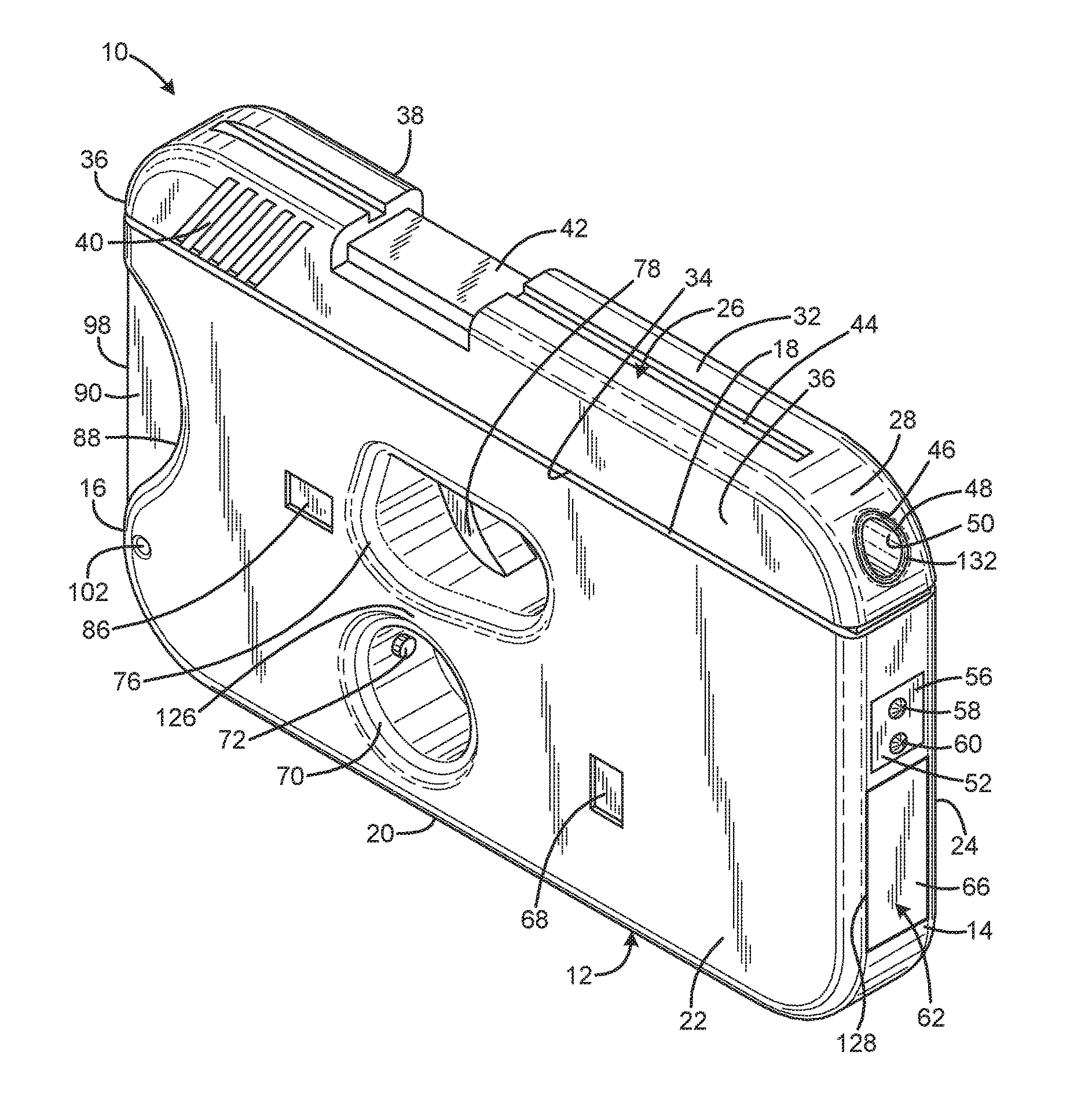
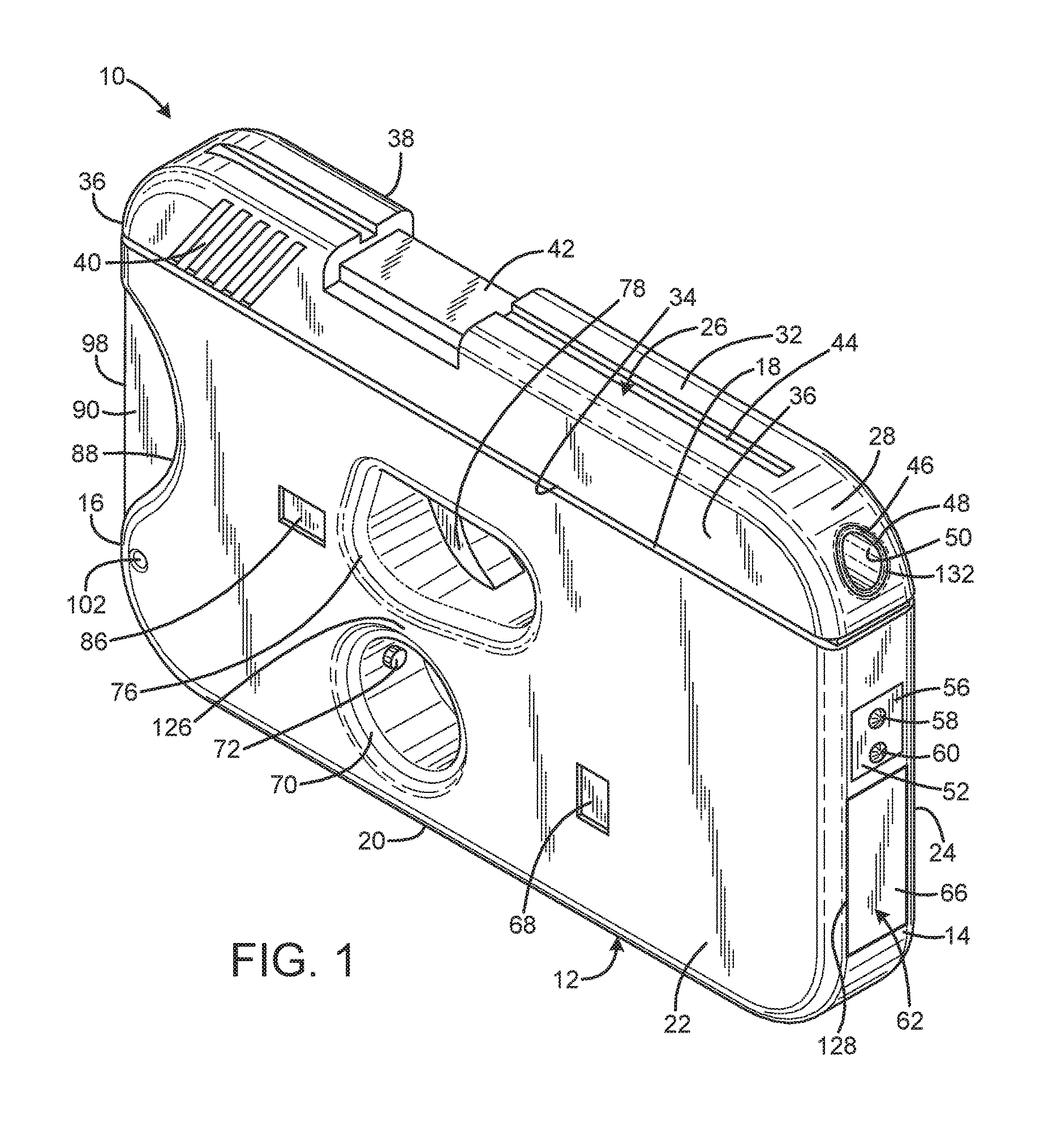
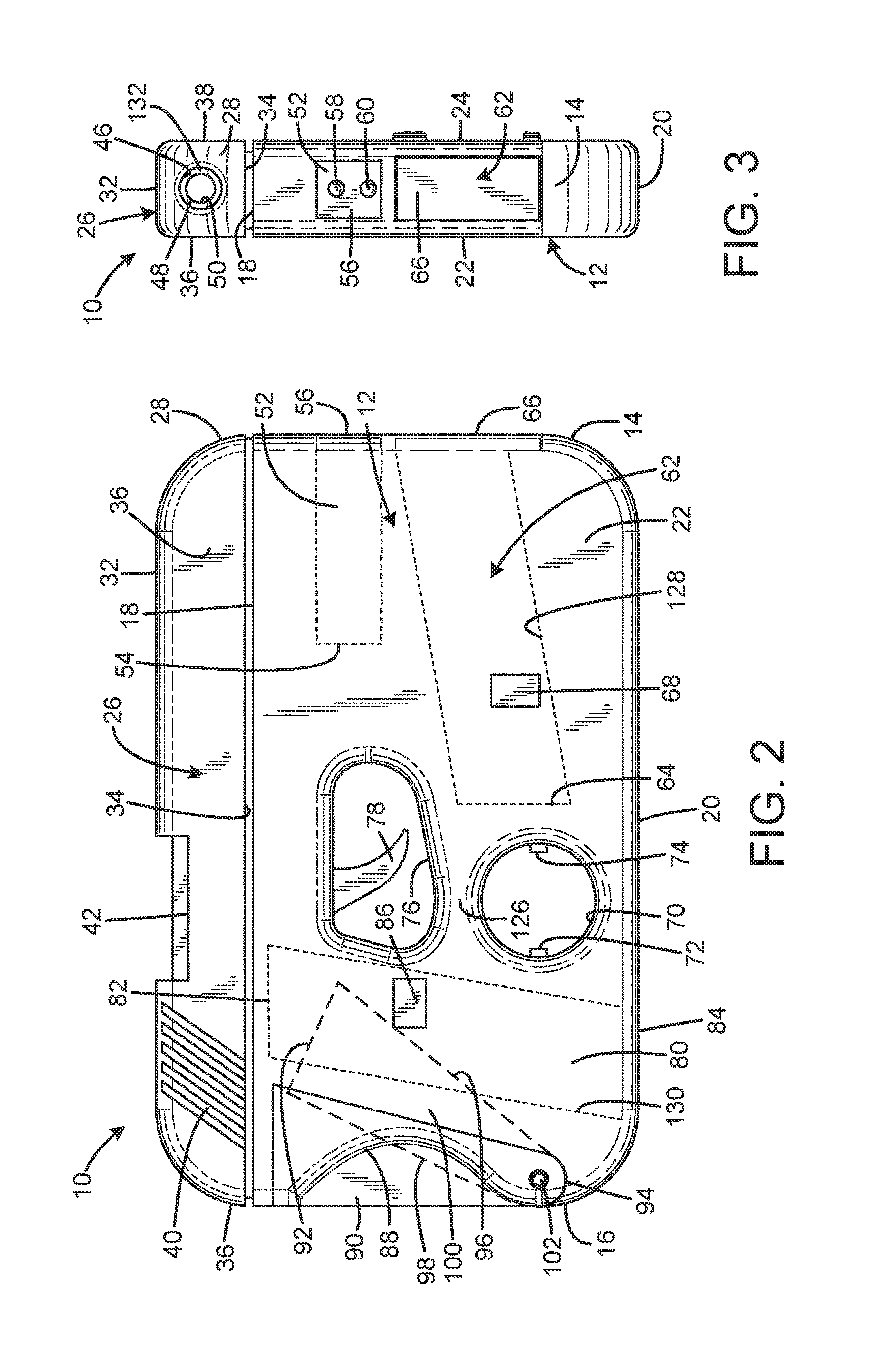
[0019]An embodiment of the pocket-carried handgun of the present invention is shown and generally designated by the reference numeral 10.

[0020]FIGS. 1-3 illustrate the improved pocket-carried handgun 10 of the present invention.

[0021]More particularly, the pocket-carried handgun has a planar body or frame 12, opposed front 14 and rear 16 edges, opposed elongated top 18 and bottom 20 edges, and opposed right 22 and left 24 major faces. In the current embodiment, the frame is a polymer frame.

[0022]A slide 26 has a bottom 34 slidably connected to the top 18 of the frame 12. The slide also has a front 28, rear 30, top 32, right 36, and left 38. In the current embodiment, the slide is made of steel. The rear of the right and left sides of the slide define slide grips 40, which are serrations that facilitate gripping of the right and left sides of the slide to pull the slide rearwardly. The top of the slide defines an ejection port 42 for ejecting spent cartridge casings and a sight 44 to...


PUM


Abstract

A pocket-carried handgun has a planar body having opposed major faces, the body having a periphery defined by opposed elongated top and bottom edges and opposed front and rear edges, the body defining a trigger aperture extending between major faces at an intermediate position away from the periphery, a trigger lever extending from the body into the trigger aperture, and the body defining a grip aperture proximate the trigger aperture and toward the bottom edge. The body may have a rectangular form. The top and bottom edges may be straight edges parallel to each other. The front and rear edges may be straight edges parallel to each other. There may be a removable plug occupying the trigger aperture. The plug may include a portion occupying the grip aperture. The plug may define a space for closely receiving a portion of the trigger lever.

Description

CROSS-REFERENCE TO RELATED APPLICATION[0001]This application claims the benefit of U.S. Provisional Patent Application No. 62 / 203,335 filed on Aug. 10, 2015, entitled “HOLSTER-LESS COMPACT POCKET CARRY HANDGUN SYSTEM,” which is hereby incorporated by reference in its entirety for all that is taught and disclosed therein.FIELD OF THE INVENTION[0002]The present invention relates to firearms, and more particularly to a compact handgun that fits into a pocket for pocket carry that does not resemble a conventional handgun.BACKGROUND OF THE INVENTION[0003]Concealed carry is the practice of carrying a firearm, usually a handgun, in public in a concealed manner. All 50 states in the US have laws allowing qualified individuals to carry certain concealed firearms in public, either without a permit or after obtaining a permit. Published statistics indicate the number of concealed carry permit holders in the United States is steadily increasing.[0004]Small caliber and small frame handguns that ...

Claims


Application Information

Patent Timeline
Patent Type & Authority Applications(United States)
IPC IPC(8): F41C9/02
CPCF41C9/02F41G1/35
Inventor TURNINGTON, MICHAEL LEE
Owner TURNINGTON MICHAEL LEE
Learn More