Push-up device and method of use

Inactive Publication Date: 2017-06-22
STEVENS ALBERT CLAY
View PDF4 Cites 7 Cited by
  • Summary
  • Abstract
  • Description
  • Claims
  • Application Information

AI Technical Summary

Benefits of technology

The present invention provides a push-up device and method that overcomes the disadvantages of previous devices. The device includes a base assembly and a ball housing with an upper surface and a concave inner surface spanning in a direction away from the upper surface of the base assembly to a lower end. The device also includes two elongated handle members that extend outwardly from the ball housing in opposing directions to a terminal free distal end. The handle members have a user-gripping section spanning at least two inches in length and of a diameter at most six inches. The device also includes a substantially rigid spherical member disposed within the ball-housing cavity and having a bottom ground-contact surface opposing the upper surface of the base assembly. The device may also include a strap disposed on the upper surface of the ball housing and a cushion coupled to the ball housing. The method of using the device involves rotating the substantially rigid spherical member against a ground surface by moving the handle members. The device and method provide improved push-up training for users.

Problems solved by technology

However, those known exercise devices do not provide users the ability to support and / or balance themselves on those devices while in a push-up configuration and in an efficient and safe manner that is conducive to providing an effective workout.
These devices and methods, however, are limited in the muscle groups that they target and do not provide much more muscular strengthening or conditioning than a typical and conventional push-up.
These devices and methods also utilize a cumbersome and difficult to store and transport bar structure that many users unappealing and undesirable.
While these devices do target various muscular groups through dynamic muscular stabilization, it is often done in an unsafe manner, as the user's arm(s) often stray too far along a translation path, putting significant strain and force on the joints of a user's upper body.
As such, these devices are often unable to be used, or impracticable for use, by the elderly, users with minimal training, and / or users with medical limitations affecting the user's upper body.

Method used


Image

  • Push-up device and method of use
  • Push-up device and method of use
  • Push-up device and method of use

Examples


Embodiment Construction

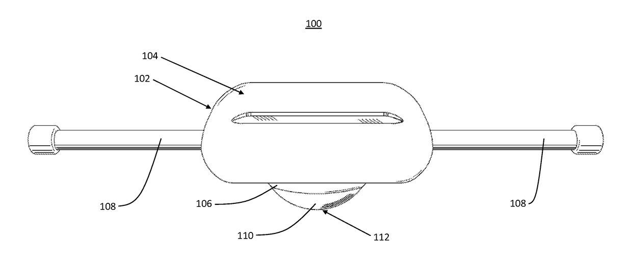
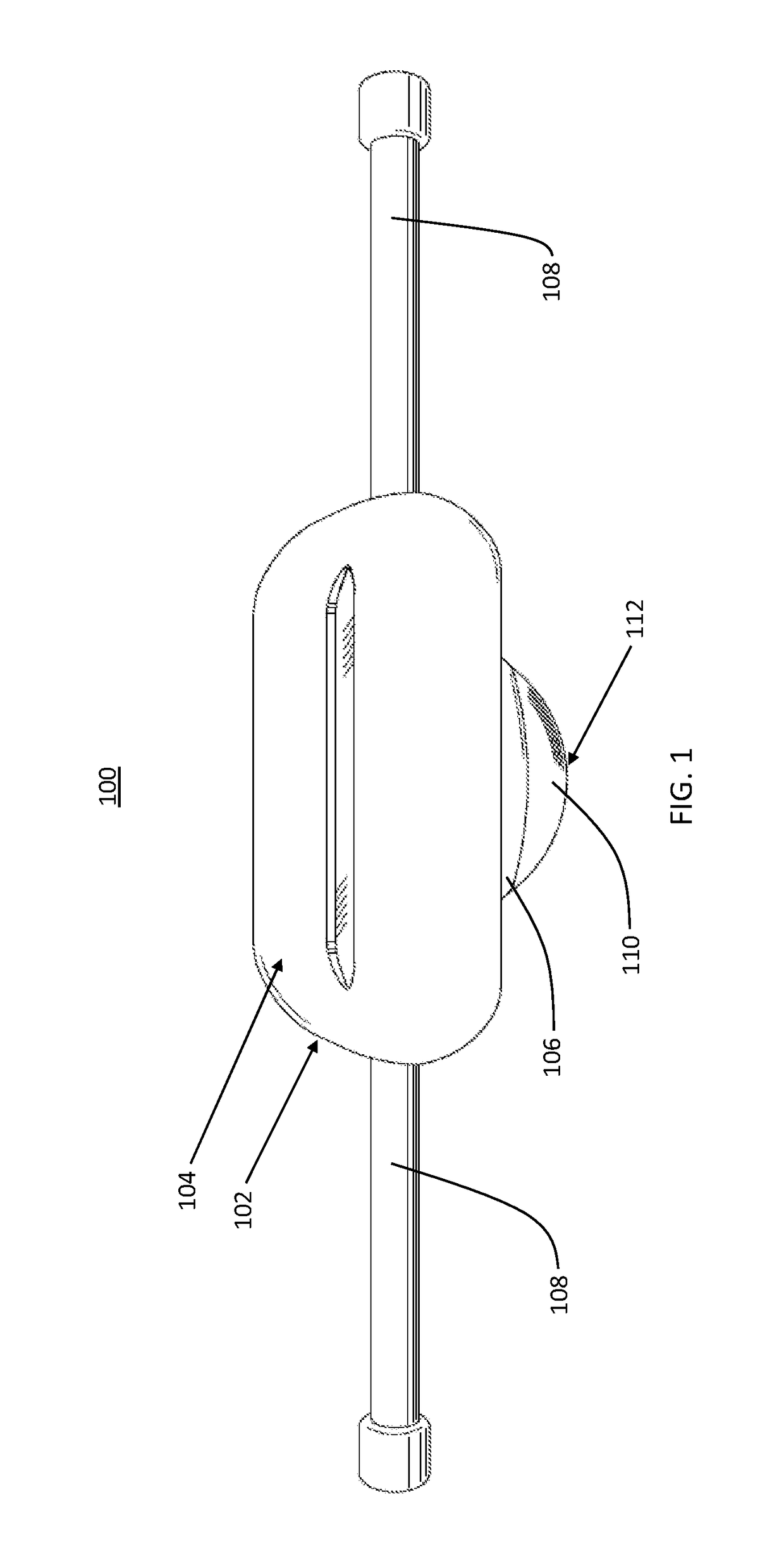
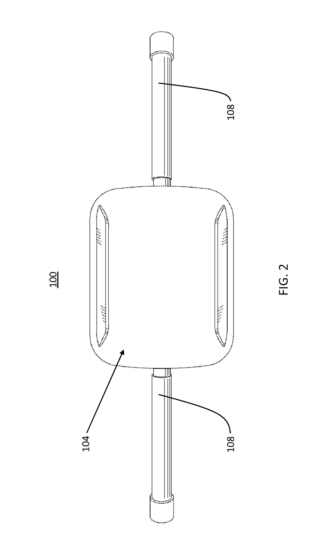
[0035]It is believed that the invention will be better understood from a consideration of the following description in conjunction with the drawing figures, in which like reference numerals are carried forward. It is to be understood that the disclosed embodiments are merely exemplary of the invention, which can be embodied in various forms. Although the invention is illustrated and described herein as embodied in a push-up exercise device, it is, nevertheless, not intended to be limited to the details shown because various modifications and structural changes may be made therein without departing from the spirit of the invention and within the scope and range of equivalents of the claims. Additionally, well-known elements of exemplary embodiments of the invention will not be described in detail or will be omitted so as not to obscure the relevant details of the invention.

[0036]Specific structural and functional details disclosed herein are not to be interpreted as limiting, but mer...


PUM


Abstract

A push-up device and method of use has been disclosed that employs the use of a spherical member that makes contact with the ground surface and supports the weight of a user when the user grasps the handle members of the push-up device and / or rests thereon. The user may balance his or her body on the push-up device while exercising. The push-up device is operable to permit the push-up device to move or translate in various directions or angles when the user is resting thereon by rotating the spherical member omni-directionally. As such, not only may a user stimulate chest and / or other upper-body muscles, but the user may also stimulate abdominals or other lower-body muscles, permitting the user to stimulate a more variety of his or her muscles through balancing himself or herself on the push-up device through the curved surface of the spherical member.

Description

CROSS-REFERENCE TO RELATED APPLICATION[0001]This application claims priority to U.S. Provisional Patent Application Nos. 62 / 413,651 filed Oct. 27, 2016, and 62 / 269,939 filed Dec. 19, 2015, the entirety of which are incorporated by reference.FIELD OF THE INVENTION[0002]The present invention relates generally to exercise devices, and, more particularly, relates to a push-up and / or abdominal exercise device.BACKGROUND OF THE INVENTION[0003]Exercise devices, including devices utilized for push-ups are well-known. However, those known exercise devices do not provide users the ability to support and / or balance themselves on those devices while in a push-up configuration and in an efficient and safe manner that is conducive to providing an effective workout.[0004]For example, some known devices and methods utilize a stationary bar that is placed on a ground surface, wherein the bar is raised above the ground surface and enables users to support them on the ground surface. These devices and...

Claims


Application Information

Patent Timeline
IPC IPC(8): A63B22/20A63B23/12A63B23/02A63B21/00
CPCA63B22/20A63B21/4035A63B23/0205A63B23/1236A63B21/4043A63B23/0211A63B26/003A63B21/0004A63B21/068A63B22/18A63B2208/0219A63B21/4047
Inventor STEVENS, ALBERT CLAY
Owner STEVENS ALBERT CLAY
Why Eureka
Try Eureka